 Tiếng
Việt
Tiếng
Việt
 Tiếng
Anh
Tiếng
Anh
 Tiếng
Nhật
Tiếng
Nhật




 Tiếng Anh

What is an automatic soldering robot? When should manual soldering be replaced in PCB assembly?

Automatic soldering robot is a suitable solution for PCB assembly processes that require consistent control of soldering position, temperature, and solder volume, but do not necessarily justify the investment in a high-capacity wave soldering machine or dip soldering system. The equipment is particularly useful for boards with a limited number of through-hole soldering points, solder joints located close to heat-sensitive components, or areas that are difficult to access using manual soldering methods. As production volume increases, maintaining consistent quality through manual soldering becomes highly dependent on operator skill. Soldering iron temperature, contact time, solder quantity, and iron angle can all vary between operators or production shifts. An automatic PCB soldering robot helps standardize these parameters through programmed settings, thereby reducing quality variation and improving process control.
1. What is an automatic soldering robot?
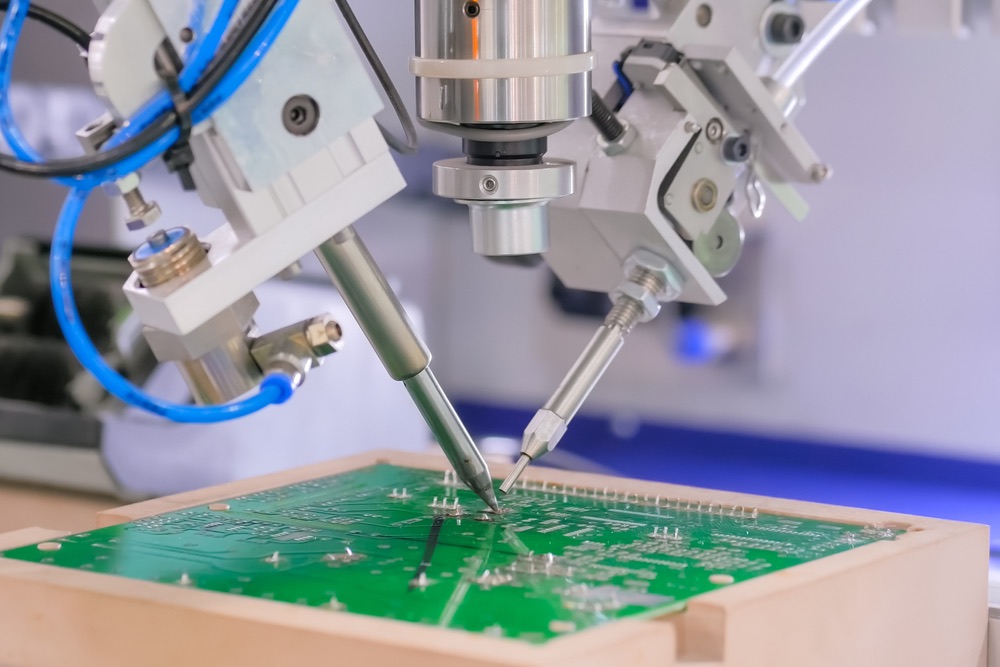
An automatic soldering robot is a machine that combines a multi-axis motion system, soldering iron, temperature control unit, and solder wire feeding mechanism to perform solder joints on PCBs according to a pre-programmed sequence. This allows the system to maintain consistent control of soldering position, temperature, contact time, and solder volume. Automatic soldering robots are commonly used in processes where manual soldering is becoming less effective, while investing in a wave soldering machine or dip soldering system is not yet necessary.
Depending on its configuration, the robot can move the soldering iron to programmed coordinates, stop at each soldering point, and perform the solder feeding – heating – soldering – retraction cycle according to predefined parameters. Unlike manual soldering, operators do not need to control every solder joint directly throughout the production process. Instead, they mainly load and fixture the PCB, select the appropriate program, inspect finished products, and monitor equipment status. More importantly, a robot does more than simply replace the operator's hand-held soldering motion. Its greater value lies in standardizing the soldering process, particularly when manufacturers need to maintain consistent quality across different production shifts or operators.
2. Structure and operating principle of an automatic soldering robot
An automatic soldering robot integrates a motion system, soldering iron, temperature control unit, and solder wire feeding mechanism into a single system. Each component performs a specific function within the soldering cycle, from securing the PCB and positioning the soldering iron accurately to controlling temperature and solder volume. In operation, the PCB is securely positioned on a fixture, after which the control system moves the soldering iron to the programmed coordinates. At each soldering point, the robot performs the soldering cycle according to the preset parameters before moving to the next position.
2.1. 3-Axis / 4-Axis motion table and PCB fixture
The motion table determines the robot's ability to position the soldering iron accurately at the required locations on the PCB. Basic systems commonly use a 3-axis soldering robot with X, Y, and Z-axis movement. Some configurations add a rotary axis to access more complex soldering positions or angles. The X and Y axes move the soldering iron to the required coordinates on the board surface, while the Z axis adjusts the soldering iron height when approaching the soldering point.
The PCB fixture securely holds the board throughout the soldering process. This component should not be overlooked because even slight movement of the board between cycles can cause the programmed coordinates to shift away from the actual pad or component lead positions. For production involving multiple product models, the fixture can be designed specifically for each PCB model or use an adjustable structure. Manufacturers should also consider fixture changeover time when evaluating the system's actual productivity.
2.2. Soldering iron, temperature controller, and solder wire feeding mechanism
The soldering iron directly transfers heat to the soldering point. Its temperature must be properly controlled according to the solder type, joint size, and component characteristics to prevent insufficient heating or excessive heat transfer to the PCB. The temperature controller maintains the soldering iron at the preset temperature. In stable production, temperature control helps reduce variation between soldering cycles, particularly compared with manual soldering where operators continuously adjust and position the soldering iron by hand.
The solder wire feeding mechanism supplies a controlled amount of solder to the soldering area according to the programmed parameters. The feed amount can be adjusted based on the requirements of each soldering point. This is particularly useful for boards with different types of component leads or varying pad sizes. For systems using flux-cored solder wire, the flux is supplied together with the solder wire during the feeding process. However, the appropriate wire diameter and flux type should still be selected based on the soldering material, required joint quality, and process requirements of each product.
2.3. Soldering program: Temperature, time, and solder volume for each point
One of the key advantages of a robot is its ability to save and recall soldering programs for different product models. Instead of relying entirely on operator technique, the process parameters can be preset and repeated in the same sequence. A program can include the coordinates of each soldering point, movement sequence, soldering iron temperature, contact time, and solder wire feed amount. For soldering points with different requirements, the parameters can also be adjusted individually rather than applying the same settings to the entire board. Programming should be carried out using actual products and verified through sample soldering tests. The process should not rely solely on theoretical parameters because heat transfer also depends on pad size, copper mass, component type, and PCB design.
Once the program has been validated, the robot can repeat the same cycle on subsequent products with greater consistency than manual soldering.
3. When Is an Automatic Soldering Robot Suitable?
An automatic soldering robot is best suited to processes with a moderate number of soldering points that require repeated operation, while the product shape or soldering locations make the use of a wave soldering machine or dip soldering machine less economically viable.
Manufacturers should select the appropriate solution based on the characteristics of the soldering points rather than production volume alone.

Boards with a limited number of through-hole soldering points
Not every PCB requires a wave soldering machine or dip soldering system. For boards with only a limited number of through-hole soldering points, processing the entire product through a high-capacity system can increase investment costs and require unnecessary floor space. In this case, a robot can handle only the soldering points that require automated processing, while other SMT processes continue to use the existing production line.
Soldering points close to heat-sensitive components or SMT components
Some through-hole soldering points are located close to SMT components that have already been assembled. In such cases, a large-area heating method may not be the optimal solution. The robot can approach each soldering point according to programmed coordinates, control the contact time, and minimize unnecessary heat exposure to the surrounding area. However, this approach still needs to be validated through actual testing. Using a robot does not automatically mean that every soldering point is safe for heat-sensitive components.
Soldering wires to boards, connector pins, or transformers
Soldering points for wires, connector pins, terminals, or certain power components may have shapes and positions that are not well suited to wave soldering. If the product design is stable and the number of models is not too large, a robot can perform these soldering points according to a fixed program. This is particularly useful for products with multiple identical soldering points. Automation helps reduce variations in soldering iron angle, solder volume, and heating time between products.
4. Comparison of manual soldering, soldering robots, and dip soldering machines
No soldering method is suitable for every type of PCB. Manual soldering, soldering robots, and dip soldering machines should be selected based on the number of soldering points, board structure, production volume, and required level of process stability.
| Criteria | Manual Soldering | Soldering Robot | Dip Soldering Machine |
|---|---|---|---|
| Consistency | Depends on operator skill | High, based on programmed parameters | High when the process is stable |
| Productivity | Low to medium | Medium | High for large numbers of soldering points |
| Labor | Requires direct operator work | Mainly operation and inspection | Operation, material loading, and process control |
| Flexibility | Very high | High for programmed products | Lower when products change frequently |
| Suitable products | Prototypes, repairs, low-volume production | Boards with selected soldering points, connectors, wires | Boards with many through-hole soldering points |
| Investment cost | Low | Medium | Higher depending on the system |
| Process standardization | Low | High | High |
| Parameter storage | Limited | Programs can be created and stored | Parameters can be controlled according to the process |
For manufacturers with low production volumes, frequent product changes, or special soldering requirements, manual soldering still offers an advantage in terms of flexibility. As production volume increases and soldering points become repetitive, robots offer clearer advantages. When a PCB has a large number of through-hole soldering points and production volume is high, a dip soldering or wave soldering system is generally more suitable for productivity. Therefore, an automatic soldering robot should not necessarily be viewed as a complete replacement for either manual soldering or wave soldering. In many production lines, it serves as an intermediate solution for automating selected soldering points.
5. Signs that a factory should switch from manual soldering to a robot
The decision to switch from manual soldering to a robot should not start with the question, “Should we buy a machine?” Instead, it should begin with the problems currently occurring in the soldering process. If quality issues, productivity, or process control increasingly depend on individual operators, the manufacturer should evaluate the potential for automation. A common sign is that the soldering defect rate varies between operators or production shifts. Even with the same PCB, solder joints may differ in solder volume, appearance, or heating time. As production volume increases, training and maintaining a team of consistently skilled soldering operators can also become a significant challenge.
Manufacturers should also consider automation when skilled manual soldering operators are difficult to recruit or retain. If operators are required to perform hundreds or thousands of repetitive soldering points every day, replacing part of the manual operation with a robot can help reduce labor pressure. Another factor is the customer's requirement for process control. When customers require manufacturers to demonstrate parameters such as soldering temperature, soldering time, or production programs, manual soldering can be difficult to standardize to the same level as an automated system. In particular, if a manufacturer has identified a group of products with stable designs, repetitive soldering points, and sufficient production volume, these products are often suitable candidates for initial robot implementation.
6. Important considerations when operating an automatic soldering robot
A robot can automate the movement process, but solder joint quality still depends on the condition of the soldering iron, soldering materials, and maintenance procedures. Manufacturers should establish clear operating and maintenance standards rather than waiting until equipment problems occur before carrying out inspections.
Regular cleaning and soldering tip replacement
An oxidized or contaminated soldering tip can reduce heat transfer efficiency. In this case, the robot may still move to the correct coordinates, but the resulting solder joint may not meet the required quality standards. Therefore, the soldering tip should be cleaned using the appropriate method and replaced when it becomes worn, oxidized, or unable to maintain stable heat transfer.
Selecting the appropriate solder wire
The solder wire must be compatible with the feeding system, wire diameter requirements, and product specifications. For flux-cored solder wire, the flux type should also be selected according to the materials and solder joint quality requirements. Solder wire should not be selected based solely on cost, as different solder wires can produce different amounts of flux and residue and have different solder flow characteristics.
Minimizing solder spatter and controlling solder feed volume
Solder spatter can occur when the temperature, flux amount, wire feeding speed, or heating time is not properly adjusted. In addition to affecting product appearance, excess solder can potentially cause short circuits between component leads with small clearances. Therefore, the program should be optimized using actual production samples. The goal is not to supply as much solder as possible, but to provide the appropriate amount of solder to form a reliable joint within a suitable heating time.
7. CNC VINA automatic soldering robot
The CNC VINA automatic soldering robot is designed for manufacturers that need to automate repetitive soldering points but do not yet require a wave soldering system or a large-scale dip soldering line. With a 3-axis motion system, the robot can position the soldering iron at predefined locations on the PCB according to the programmed sequence. The fixture securely holds the board, while the solder feeding system and temperature control system work together to perform the soldering cycle according to the preset parameters. This solution is particularly suitable for applications involving selected through-hole soldering points, connector pins, wires, or other locations that require consistent soldering but do not have enough soldering points per board to justify the use of a wave soldering machine.

Before selecting the equipment configuration, CNC VINA can assess the PCB dimensions, number and location of soldering points, component types, production volume, cycle time, and quality requirements to determine the appropriate automation solution. This step is important because the investment efficiency of a soldering robot depends not only on its movement speed but also on PCB loading and fixturing time, product model changeover time, and the actual soldering cycle. With experience in implementing industrial automation solutions, CNC VINA focuses on integrating the soldering robot into the existing production process rather than treating the equipment as a separate standalone operation. Manufacturers can combine the robot with dedicated fixtures, material feeding systems, and downstream inspection processes to gradually increase the level of automation across the PCB assembly line.
If your factory currently relies on manual soldering and is experiencing skill-dependent defects, increasing production volume, or the need for more consistent control of soldering parameters, an automatic soldering robot or a 3-axis PCB soldering robot can be a suitable first step toward automation before investing in a full-line wave soldering system. Contact CNC VINA to evaluate the configuration of a 3-axis PCB soldering robot based on your actual products and production process.
VIETNAM TECHNOLOGY APPLICATION & CNC JOINT STOCK COMPANY
Factory: Song Cung Industrial Cluster, Dong Thap Commune, Dan Phuong District, Hanoi, Vietnam.
Office: Rox Tower Goldmark City, 136 Ho Tung Mau Street, Phu Dien Ward, Hanoi, Vietnam.
Phone: +84 916 639 355 / +84 915 744 664
Website: www.cncvina.com.vn ; www.cncvina.net