 Tiếng
Việt
 Tiếng
Anh
 Tiếng
Nhật



 Tiếng Anh

Common types of part feeding systems for automatic assembly machines

Automatic part feeding systems for assembly machines are essential components in automated production lines, responsible for storing, arranging, orienting, and supplying parts to subsequent production stages. Using a suitable feeding system helps ensure a continuous supply of components, reduce manual operations, and improve the operating efficiency of assembly machines. Depending on the shape, dimensions of the parts, and required production capacity, businesses can choose from various feeding methods, such as step feeders, flexible part feeders, and centrifugal feeders. Each type of equipment has its own operating principle and application range, making it suitable for specific production requirements. So, what are the characteristics and applications of the most common types of automatic part feeding systems for assembly machines today? Let's explore the details with CNC VINA in the following article.
1. Functions of part feeding systems in automatic assembly machines
Automatic part feeding systems are devices designed to store, arrange, sort, orient, and distribute parts to designated working positions along a production line. These systems are commonly integrated into assembly machines, inspection machines, or automated production systems to ensure that parts are continuously supplied according to the requirements of the subsequent production processes.
Depending on their structure and operating principles, part feeding systems can perform one or more of the following functions:
-
Part storage: Hold a certain quantity of components to ensure a continuous supply to the machine during operation.
-
Arrangement and sorting: Separate randomly positioned parts into individual components.
-
Orientation and positioning: Align parts in the correct direction, orientation, and position before transferring them to the next production stage.
-
Transportation and distribution: Transfer parts to a standby position or directly to gripping, assembly, and inspection mechanisms.
-
Feeding process control: Work in combination with sensors and control systems to maintain an appropriate part supply, preventing shortages or overlapping parts.
Selecting the right part feeding system helps improve production line continuity, reduce waiting time, minimize collisions between parts, and enhance the overall operating efficiency of the entire system.
2. Common types of part feeding systems for assembly machines
Today, part feeding systems are designed with various operating principles to accommodate the characteristics of different products. Below are some of the most commonly used types of equipment in automatic part feeding systems.
2.1. Step feeder
Characteristics of a step feeder
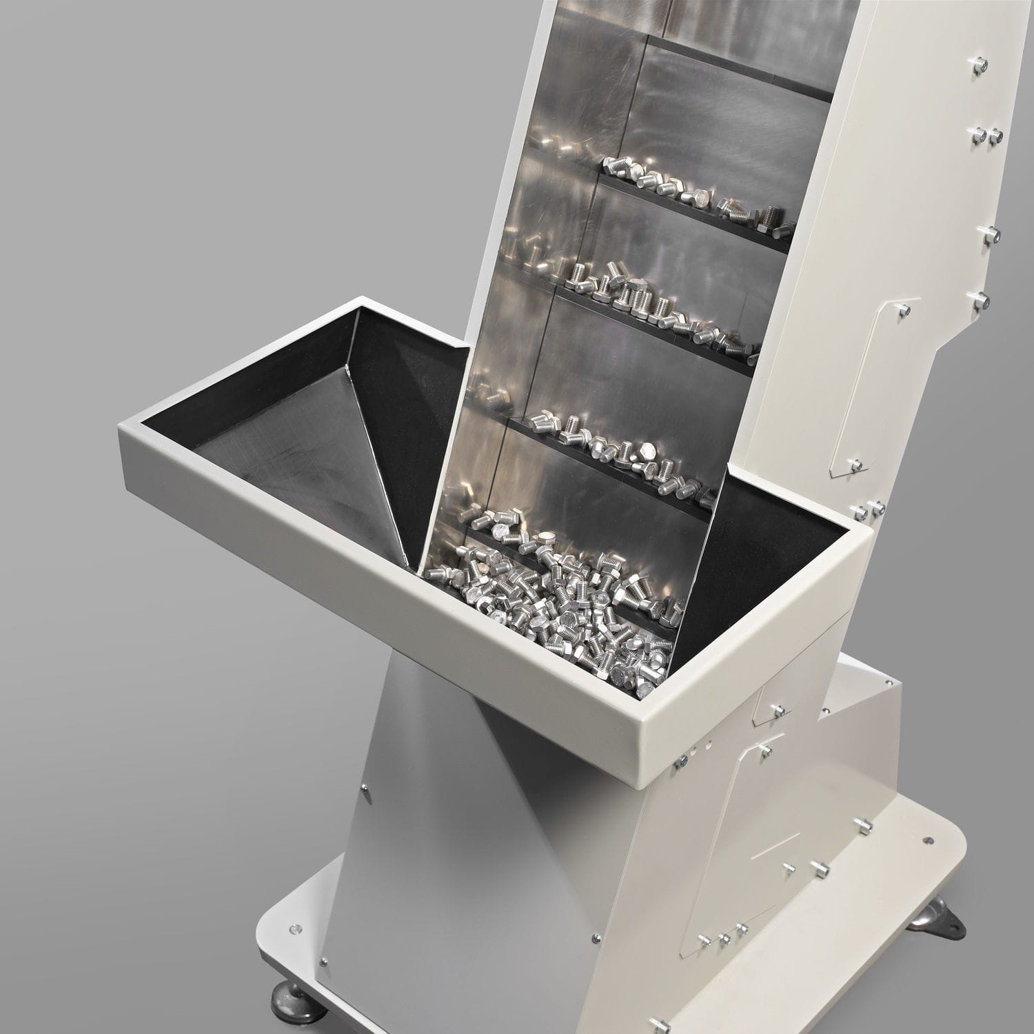
A step feeder uses a step-by-step lifting mechanism to move parts from a storage hopper onto a guide track. During this process, the parts pass through specially designed orientation and sorting mechanisms based on their shapes and dimensions.
Trapping and guiding mechanisms are responsible for retaining, rejecting, or adjusting parts that are not in the correct orientation. As a result, parts are discharged at the end of the track in a predetermined orientation and are ready to be transferred to the next production stage.
Step feeders are commonly used for feeding metal components such as screws, bolts, cylindrical parts, and certain small-sized products. This equipment is widely applied in the automotive, motorcycle, mechanical engineering, electrical, and electronics industries.
Advantages of a step feeder
- Reduced friction and impact: Unlike systems that rely on continuous vibration to transport parts, step feeders help minimize friction and collisions between components.
- Product surface protection: Suitable for screws and metal components that require protection against scratches or damage to their surface coatings.
- Lower noise levels: The step-by-step lifting mechanism helps reduce operating noise compared to some traditional vibratory feeding methods.
- Improved equipment durability: The hopper and guiding surfaces are less exposed to continuous impacts, helping reduce wear during operation.
- Stable part feeding: Components are lifted and transferred onto the guide track step by step, allowing better control of the feeding process.
2.2. Flexible part feeder using a camera and pick-and-place robot (Flex feeder)
Characteristics of a flexible part feeder
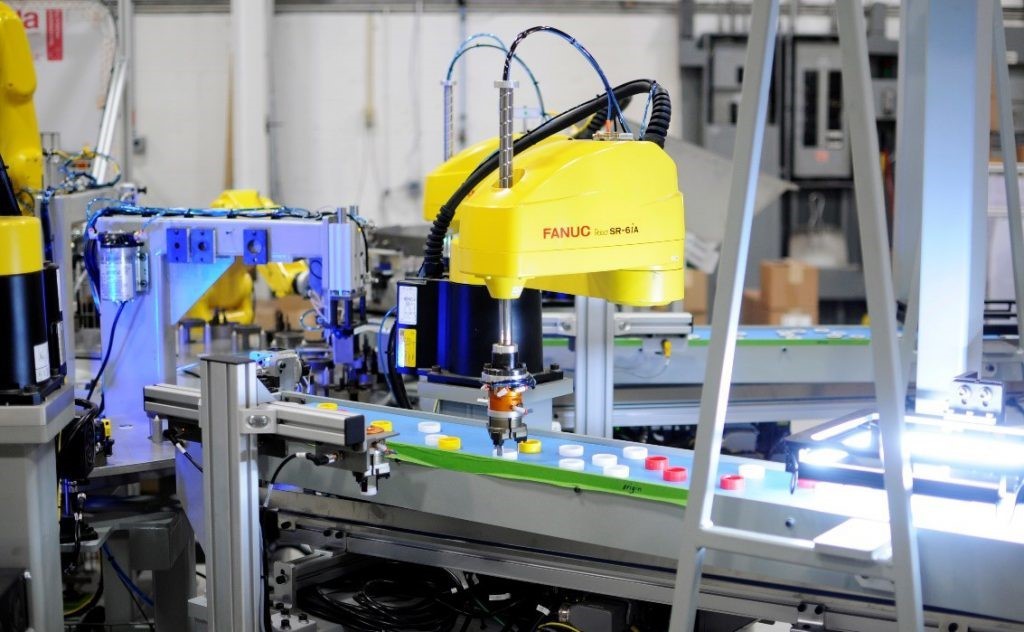
A flexible part feeder is a feeding system that combines a part feeder, an industrial camera (Vision system), and a pick-and-place robot. Instead of relying entirely on fixed mechanical guiding mechanisms, the system uses a camera to recognize part shapes and determine the position and orientation of each component.
After receiving data from the Vision system, the robot determines the picking coordinates, picks up the part, and places it at the required position on the assembly machine.
A typical Flex feeder system consists of the following main components:
- Flexible part feeder: Holds and distributes components across the feeding surface.
- Vision camera system: Recognizes products and determines the position and orientation of each component.
- Pick-and-place robot: Picks up and transfers parts to the working position.
- Controller: Processes signals, manages programs, and coordinates the operation of all equipment.
-
The system can communicate with robots and other automation equipment through I/O signals or commonly used industrial communication protocols.
Advantages of a flexible part feeder
- Adaptability to different products: Can feed components with various shapes and dimensions within the same system, depending on its recognition and pick-and-place capabilities.
- Fast model changeover: When switching between products, operators can select a pre-configured program without making extensive changes to mechanical guiding mechanisms.
- Reduced setup time: Minimizes the need to manufacture and replace dedicated fixtures and guide tracks for each product type.
- Recognition of complex parts: The Vision camera helps identify the position and orientation of components with irregular shapes or randomly distributed arrangements.
- Easy automation integration: Can be integrated with industrial robots, collaborative robots, and control systems used in smart factories.
Flexible part feeders are suitable for production lines handling multiple product models, frequent product changes, or diverse part feeding requirements. However, system performance depends on the camera's recognition capabilities, the surface characteristics of the components, and the robot's gripping capabilities.
2.3. Vibratory feeder
Characteristics of a vibratory feeder
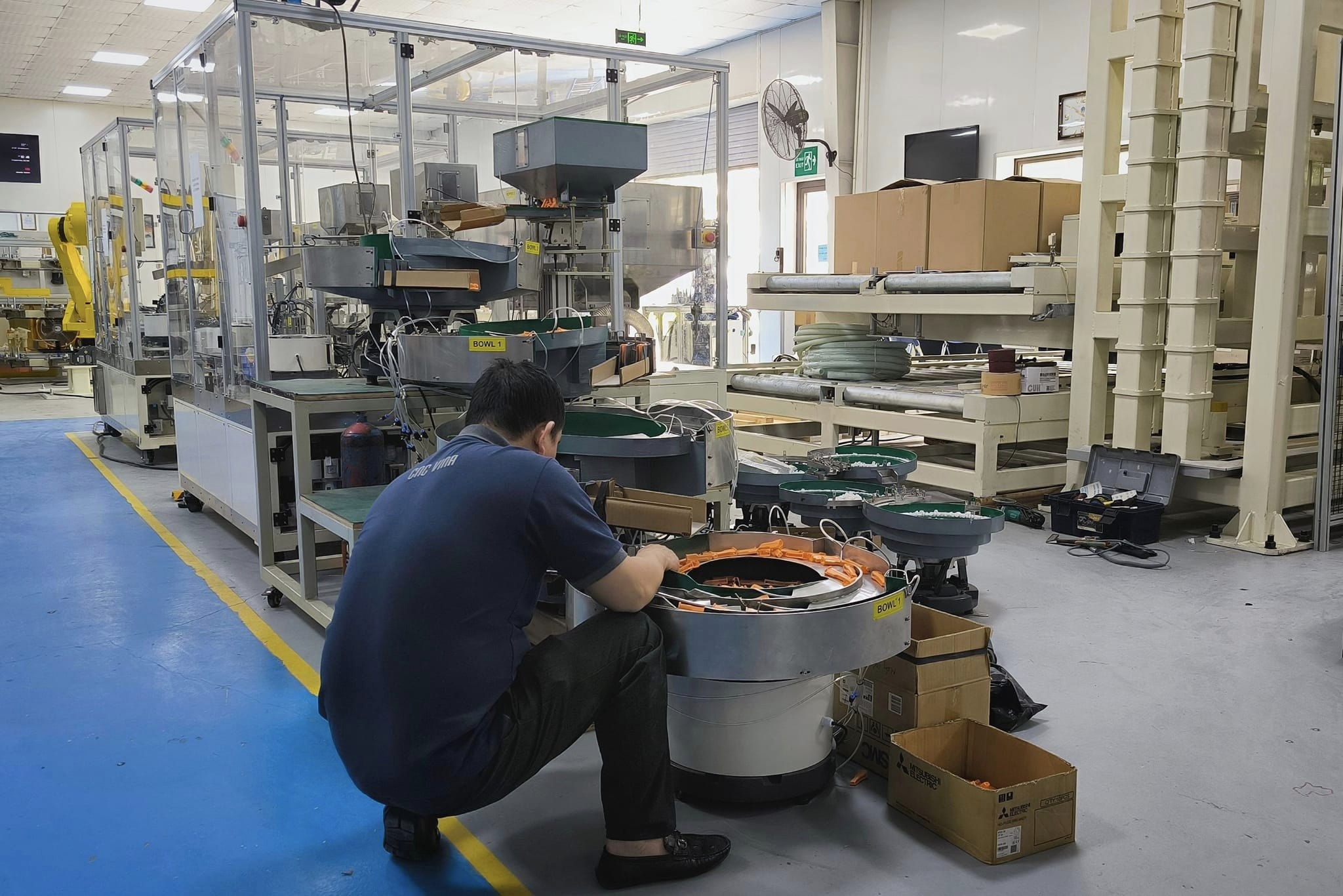
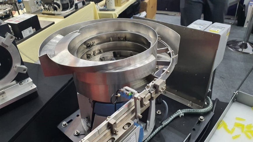
An automatic vibratory bowl feeder, also known as a vibratory feeder or vibratory bowl, is one of the most common devices used in automatic part feeding systems. It uses an electromagnetic vibration mechanism or a suitable vibration-generating mechanism to move components from the bottom of the bowl upward along a spiral guide track.
During the vibration process, parts move along the guide track and pass through sorting and orientation mechanisms designed according to their shapes and dimensions. Parts that are not in the correct orientation may be rejected or returned to the storage area for further sorting.
Once properly oriented, the parts move toward the vibratory bowl feeder's outlet and are transferred to a linear vibratory feeder track, a feeding mechanism, or directly to the assembly machine.
Advantages:
-
Relatively simple structure: Easy to install, operate, and integrate with other automation equipment.
-
Continuous part feeding: Capable of supplying components in a steady flow to meet the requirements of various production processes.
-
Compact design: Available in different sizes and configurations, making it convenient to install within machine spaces.
-
Wide range of applications: Can be used to feed screws, bolts, springs, electronic components, and various other mechanical parts.
-
Easy integration with control systems: Can be equipped with sensors to monitor part levels, detect full conditions, and send control signals to stop or start the feeder.
Limitations:
Vibratory bowl feeders generally require guide tracks and orientation mechanisms specifically designed for each product type. Therefore, when changing product models, businesses may need to replace or adjust certain mechanical components.
In addition, products with highly symmetrical shapes, large dimensions, or geometric features that are difficult to distinguish may pose challenges during the orientation process. For components that are prone to scratches, vibration amplitude and contact materials should be carefully considered to minimize collisions during feeding.
2.4. Linear feeder
Characteristics of a linear feeder
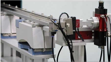
A linear feeder is a device that uses vibration to transport components from the input end to the output position along a straight guide track. It is typically installed downstream of a vibratory bowl feeder to receive, maintain, and transfer parts to the standby position of the assembly machine.
The linear vibratory feeder track is designed with a guide path whose shape and dimensions are suitable for each product type. During operation, the vibration mechanism moves components sequentially in a specific direction, helping prevent overlapping and inconsistent part feeding.
Products commonly supplied by linear feeders include springs, screws, bolts, washers, rivets, electronic components, and small mechanical parts.
Advantages of a linear feeder
-
Stable part transportation: Ensures that components move continuously and orderly along the guide track.
-
Extended feeding distance: The length of the vibratory track can be designed to suit the distance between the vibratory bowl feeder and the part receiving position.
-
Easy installation: Can be connected to vibratory bowl feeders, sensors, and other feeding mechanisms.
-
Maintained product orientation: Helps prevent changes in the orientation of components during transportation.
-
Improved operating efficiency: Can be integrated with sensors to monitor the part quantity at the outlet and control the vibratory bowl feeder's start and stop functions when necessary.
In practice, linear vibratory feeders rarely operate independently. Instead, they are commonly combined with vibratory bowl feeders to form a complete part feeding system for automatic assembly machines.
2.5. Centrifugal feeder
Characteristics of a centrifugal feeder
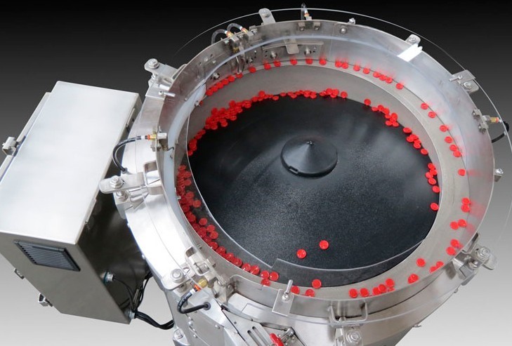
A centrifugal feeder uses a rotating feeding disc driven by an electric motor to move components from the center toward the outer edge through centrifugal force.
As the disc rotates, components move toward the bowl wall or peripheral area. Here, the guiding system and sorting mechanisms adjust the orientation of the parts before transferring them to the output track.
Unlike traditional vibratory bowl feeders, centrifugal feeders do not use vibration to transport and orient components. Instead, they utilize the rotational motion of the disc to create a continuous flow of parts.
Advantages of a centrifugal feeder
- High feeding speed: Can meet the requirements of high-output applications, with some configurations achieving speeds of up to 1,000 parts per minute.
- Low-vibration operation: Minimizes the effects of vibration on products during the feeding process.
- Reduced collisions between parts: Can be suitable for small, delicate components or products that require scratch prevention when properly designed.
- Continuous part feeding: The rotational motion helps transfer components to the sorting area and outlet at a stable speed.
Centrifugal feeders are often considered for production lines requiring high output and the handling of large quantities of components within a short period. However, equipment selection should be based on the shape, dimensions, material, and movement characteristics of the products.
3. Criteria for selecting a suitable part feeding system for assembly machines
Each type of part feeding system has its own operating principle and application range. Therefore, to select suitable equipment, businesses need to consider product characteristics, production requirements, and integration capabilities with the machine system.
Some important factors to consider include:
-
Product characteristics: The dimensions, weight, shape, material, and orientation requirements of components directly affect the design of the storage hopper, guide track, and feeding mechanism.
-
Production capacity requirements: High-output production lines with short cycle times require a part feeding system with a speed that matches the operating cycle of the assembly machine.
-
Surface quality requirements: For products that are prone to scratches, deformation, or damage to special coatings, priority should be given to feeding methods that minimize friction and collisions.
-
Model changeover capability: If the production line frequently switches between different product types, flexible feeding systems or designs that allow quick changeovers should be considered.
-
Installation space: The equipment dimensions, outlet position, and connection distances must be compatible with the overall layout of the assembly machine.
-
Control system integration: The part feeding system should be capable of connecting with PLCs, sensors, robots, and related equipment to ensure synchronized operation.
-
Investment and maintenance costs: Manufacturing costs, product changeover expenses, maintenance requirements, and equipment service life throughout its operation should all be evaluated.
Equipment selection should not be based solely on feeding speed but should also consider its ability to meet the entire machine operating cycle. A suitable feeding system must ensure that components are delivered to the correct position, in the correct orientation, and at the right time to prevent interruptions in the assembly process.
Part feeding systems for assembly machines are important components that help ensure a continuous and accurate supply of parts throughout the production process. Each feeding method, including step feeders, flexible feeders, vibratory bowl feeders, linear feeders, and centrifugal feeders, has its own characteristics and is suitable for different production conditions. Equipment selection should be based on product characteristics, production capacity requirements, and production line organization. A properly designed part feeding system not only helps improve operating efficiency but also reduces manual operations and minimizes production interruptions. In addition, integration capabilities with robots, sensors, and control systems are important factors to consider when developing an automated production line. CNC VINA provides design and manufacturing solutions for vibratory bowl feeders and linear vibratory feeders based on product characteristics and actual business requirements. These solutions provide a foundation for developing suitable part feeding systems that meet the operating requirements of assembly machines and industrial production lines.