 Tiếng
Việt
Tiếng
Việt
 Tiếng
Anh
Tiếng
Anh
 Tiếng
Nhật
Tiếng
Nhật



 Tiếng Anh

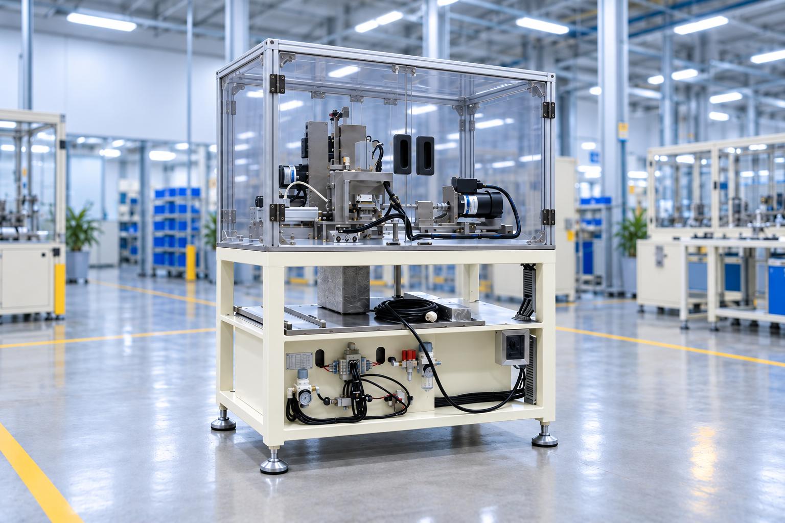
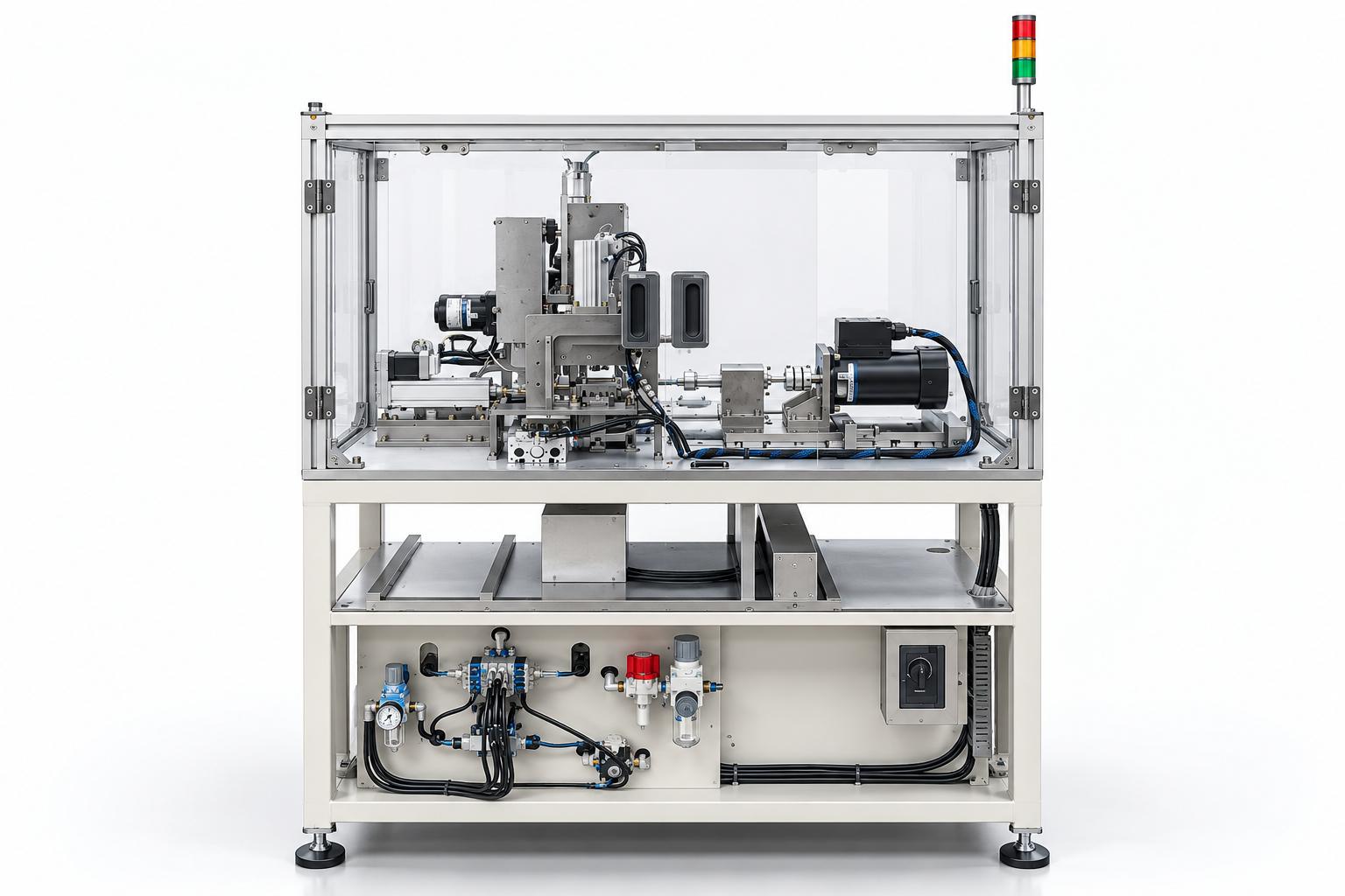
Automatic rubber tube cutting machine
A rubber tube cutting machine is a specialized piece of equipment designed to cut tubular or cylindrical rubber products to specified lengths and at defined cutting positions. In the configuration described in the technical documentation, the operator manually loads the product into the feeding unit, selects the appropriate program, and starts the cycle. The machine then automatically performs the feeding, clamping, spindle rotation, cutting, and air-blowing operations in a predefined sequence controlled by the system.
VIETNAM CNC & TECHNOLOGY APPLICATION JOINT STOCK COMPANY
Hotline: +84.916 63 9355 / +84.915 74 4664
Email: Sales01@cncvina.com.vn / Sales03@cncvina.com.vn
Product description

A rubber tube cutting machine is specialized equipment designed to cut tubular or cylindrical rubber products to specified lengths and at predetermined cutting positions. In the configuration described in the technical documentation, the operator loads the product into the feeding unit, selects the appropriate program, and starts the cycle. The machine then automatically performs the feeding, clamping, spindle rotation, cutting, and air-blowing operations in a predefined control sequence.
The rubber tube cutting machine is designed and manufactured by CNC VINA to meet the specific requirements of each product. The feeding unit, clamping jaws, cutting blade position, fixtures, and control program can be adjusted or modified to accommodate different product lengths, diameters, and cutting requirements.
Applications of rubber tube cutting machines in industrial manufacturing
This equipment is suitable for production processes that require technical rubber tubes or cylindrical rubber components to be cut repeatedly to specified dimensions. The machine can be installed as a standalone workstation in a processing area or integrated into an existing production line.
-
Cutting rubber tubes to specified lengths before assembly or packaging.
-
Trimming excess material from tube ends to achieve consistent product lengths.
-
Processing tubular or cylindrical rubber components in various sizes within the machine's designed operating range.
-
Supporting technical rubber component manufacturing lines that require repeatable cutting operations and precise control of cutting positions.
-
Automating clamping, rotation, cutting, and air-blowing operations in processes where products are manually loaded into the machine.
Machine structure and main functional units
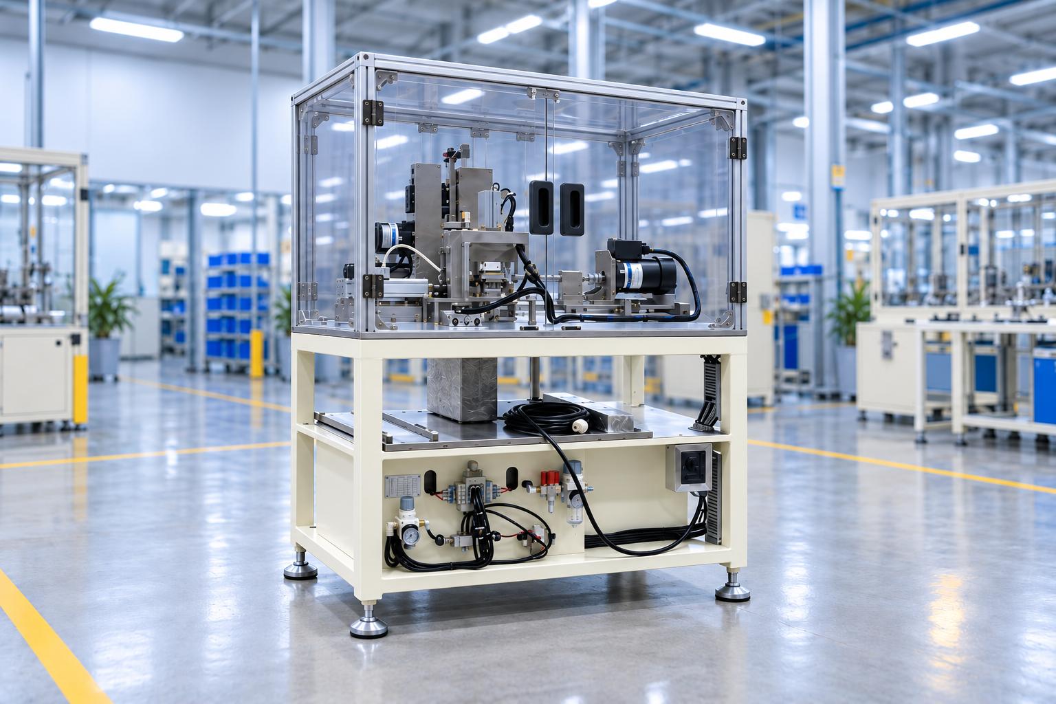
Machine structure and main functional units
The feeding unit receives rubber tubes from the operator and moves them to the clamping position. The feeding length can be adjusted using a quick-adjust hand knob to accommodate different product models.
Product clamping unit
The clamping unit securely holds the product during rotation and cutting. The clamping jaws can be replaced according to the product diameter. The clamping mechanism uses a pneumatic cylinder and a stroke sensor to confirm the operating status before proceeding to the next step.
Main spindle unit
The main spindle unit provides rotational movement to the product during processing. The motor and transmission mechanism are mounted on the machine table and work in coordination with the clamping unit and cutting blade to maintain stable rotation.
Cutting unit
The cutting unit cuts the product at the specified position. During product changeover, the blade position is adjusted using an alignment jig to ensure proper alignment and positioning relative to the clamping unit, making it easier to switch between different product sizes.
Excess-end removal and air-blowing unit
After cutting, the removal mechanism handles the excess end material. The air-blowing system is supplied through a separate filtration branch to help clean the processing area and remove scrap material from the cutting zone.
Product and scrap collection tray
The machine is equipped with collection areas for finished products and scrap material, located beneath or beside the processing area. This arrangement separates the cut materials from the main mechanisms and makes collection easier for the operator.
Machine frame and safety guards
The processing area is enclosed by a frame and transparent protective panels to restrict direct access to the cutting blade, rotating spindle, and moving mechanisms. The machine is equipped with a signal tower light to indicate operating status, as well as safety guard doors for operation, inspection, and maintenance.
Pneumatic, electrical, and control systems
The pneumatic system uses separate filter-regulator units for the cylinders and air-blowing nozzle. The electrical cabinet and control panel manage operating modes, product selection, sensor status, and the operating sequence. The PLC can be supplied by Keyence, Mitsubishi, Siemens, or an equivalent manufacturer, depending on the customer's requirements.
Key features of the automatic rubber tube cutting machine
-
Integrates product feeding, clamping, rotation, cutting, and air blowing into a single controlled cycle.
-
The feeding unit can be adjusted to suit the product length using a quick-adjust hand knob.
-
The clamping jaws and cutting blade position can be changed to accommodate different product diameters and dimensions.
-
Uses a cutting alignment jig during product changeover to help ensure accurate blade positioning.
-
Provides a manual operation mode for checking individual units after product changeover before starting production.
-
Sensors monitor mechanism travel and product status throughout the operating cycle.
-
The processing area is enclosed by safety guards to separate the operator from the machine's moving mechanisms during operation.
-
The machine has a compact design and an operating height of approximately 900 mm, making it suitable for installation at production workstations.
Operating principle
The operator loads the product into the feeding unit and selects the corresponding program. Once the machine is started, it performs the processing cycle according to the programmed sequence.
Step 1: The operator loads the rubber tube into the feeding unit.
Step 2: The feeding unit moves the product to the clamping position. Sensors confirm the product status before processing begins.
Step 3: The clamping unit secures the product while the main spindle rotates it according to the programmed cycle.
Step 4: The cutting unit moves into position and cuts the product.
Step 5: The excess-end removal mechanism and air-blowing nozzle remove excess material and clean the cutting area.
Step 6: All mechanisms return to their initial positions, allowing the operator to load the next product.
Product changeover
The machine is designed to accommodate different product models within its specified operating range. Before changing products, the system is switched to manual mode, and the corresponding program is then selected on the control panel.
-
Feeding unit: Adjust the position according to the product length using the quick-adjust hand knob.
-
Clamping unit: Replace the clamping jaws to match the product diameter and reinstall the excess-end removal mechanism.
-
Cutting unit: Use an alignment jig to align the cutting blade, secure the fixture, and then remove the jig.
-
After changeover: Operate each unit in manual mode to check movement, prevent jamming, and verify that all components are correctly positioned.
Control and safety
The control panel allows the operator to select product models and operating modes. The pneumatic mechanisms, motor, clamping unit, and cutting blade work together according to the programmed sequence. Sensors confirm the positions of the mechanisms before the machine proceeds to the next step.
The moving components and cutting area are enclosed within a guarded zone. The pneumatic system is regulated to the specified operating pressure, while the electrical cabinet uses a 24 V DC control supply for control circuits and sensors.

Technical specifications of the rubber tube cutting machine
The following specifications are taken from the machine described in the technical documentation. When designing the machine for other products, the overall dimensions, clamping unit, cutting blade, cycle time, and product changeover range can be adjusted to meet actual requirements.
| Item | Specification |
|---|---|
| Machine type | Rubber tube cutting machine |
| Product feeding method | Products are manually loaded into the feeding unit |
| Overall dimensions | L480 × W943 × H1500 mm |
| Operating height | 900 ± 50 mm from the floor |
| Main power supply | Single-phase, AC 220 V, 50 Hz |
| Power supply capacity | DC 24V |
| Control electrical system | 0.4 - 0.6MPa |
| Pneumatic pressure | 6.5 s/product |
| Cycle time | Product feeding, clamping, main spindle rotation, cutting, and air blowing |
| Main units | Adjustable feeding unit, replaceable clamping jaws, and adjustable cutting unit |
| Product changeover capability | Industrial PLC – Keyence, Mitsubishi, Siemens, or equivalent |
| Control system | Industrial control panel |
| Operator interface | Frame and transparent safety guards surrounding the processing area |
Maintenance of the main units
Regular inspections should focus on sliding mechanisms, bolts, bearings, motors, and cylinders. Check for slide jamming, the condition of sliding surfaces, looseness in mechanical connections, unusual noise, and motor temperature. The air supply and cylinder connections should also be inspected.
Sliding surfaces should be cleaned and lubricated periodically. Rotating and transmission mechanisms should be checked for bearing condition, excessive play, and overall operating performance to maintain the stability of the cutting cycle.
Frequently asked questions
Does the machine automatically feed rubber tubes?
In the configuration described in the documentation, the operator manually loads the product into the feeding unit. Once the machine starts, the product transfer, clamping, rotation, cutting, and air-blowing operations are performed automatically according to the programmed cycle.
Can the machine cut rubber tubes of different sizes?
Yes, within the machine's designed operating range. During product changeover, the feeding unit must be adjusted, the clamping jaws must be replaced to match the product diameter, and the cutting blade position must be readjusted.
What electrical power supply and compressed air are required?
The documented configuration uses a single-phase AC 220 V, 50 Hz power supply, a 24 V DC control supply, and compressed air at approximately 0.4–0.6 MPa.
What is the machine's cycle time?
The general arrangement drawing specifies a cycle time of approximately 6.5 seconds per product for the documented machine configuration. The actual cycle time depends on the product and processing requirements.
Does the cutting blade need to be realigned when it is replaced?
Yes. The documentation specifies the use of a cutting alignment jig to help align the blade correctly. The cutting fixture is then secured before the jig is removed.
Which PLC brands can be used with the machine?
The PLC can be selected from Keyence, Mitsubishi, Siemens, or equivalent manufacturers according to the customer's control system requirements.
Can the machine be designed for other types of rubber tubes?
Yes. The feeding structure, clamping unit, and cutting mechanism can be customized according to product dimensions and material characteristics after evaluating the actual product samples and cutting requirements.
The rubber tube cutting machine is an automation solution designed to process and cut rubber tubes to specified lengths, positions, and technical requirements, helping improve product consistency and optimize manufacturing processes. The machine integrates functional units such as product feeding, clamping, spindle rotation, cutting, excess-end removal, air blowing, and PLC control. These units operate in a programmed sequence to perform a stable cutting cycle. With an adjustable feeding unit, replaceable clamping jaws, adjustable cutting blade position, and configurable operating programs, the machine can accommodate different rubber tube models within its designed operating range. In addition, sensors monitor the status of the mechanisms, safety guards enclose the processing area, and an intuitive control interface facilitates operation and maintenance. CNC VINA designs and manufactures rubber tube cutting machines to meet the actual requirements of each business, including product dimensions, feeding methods, fixture configurations, control systems, and production line integration. This solution is suitable for manufacturers of technical rubber components seeking to standardize cutting operations, reduce manual tasks, and improve overall industrial production efficiency.