 Tiếng
Việt
 Tiếng
Anh
 Tiếng
Nhật




 Tiếng Anh

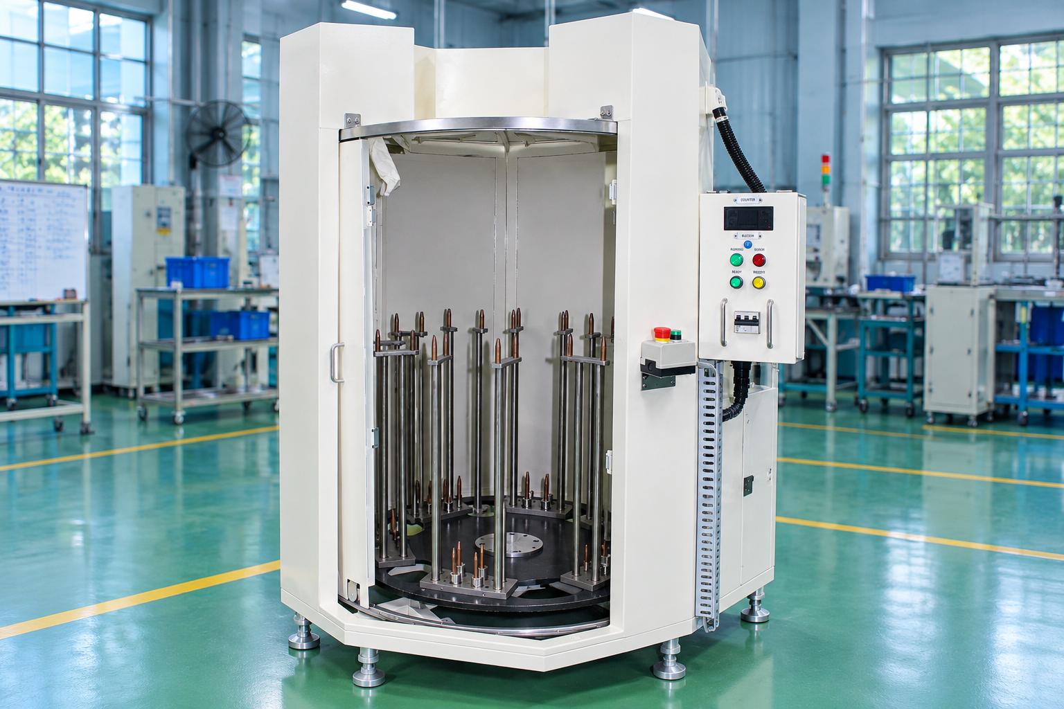
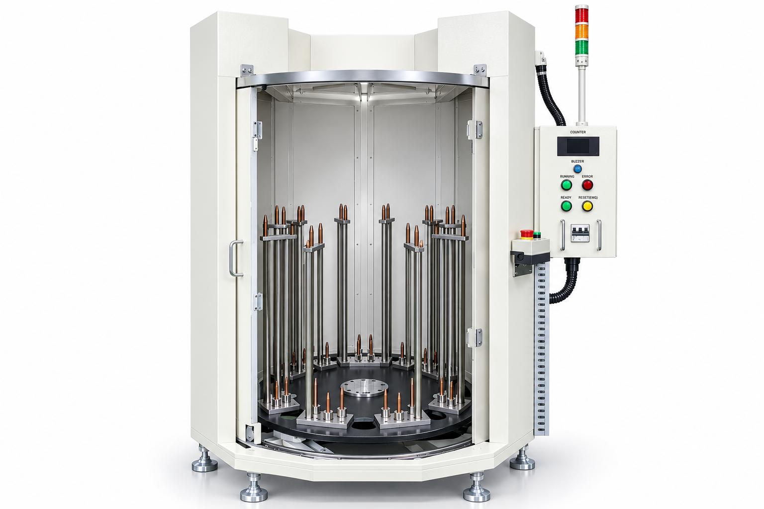
Rotary table cooling machine for heat-treated products
CNC VINA’s product cooling machine is designed to cool components after heating or removal from a furnace. The machine uses a rotary table equipped with fixture assemblies and connects to an external cooling unit to supply the cooling medium to the processing chamber. The operator manually loads the hot products and unloads the cooled products, while the rotary mechanism and dwell time are controlled according to a predefined cycle.
This semi-automatic configuration is suitable for factories that need to position products at designated locations, maintain a consistent cooling sequence, and transfer components to the next production stage. The actual configuration should be selected based on the input temperature, required final temperature, component characteristics, and cooling supply capacity.
VIETNAM CNC & TECHNOLOGY APPLICATION JOINT STOCK COMPANY
Hotline: +84.916 63 9355 / +84.915 74 4664
Email: Sales01@cncvina.com.vn / Sales03@cncvina.com.vn
Product description

Rotary table cooling machine for products after heating is a solution designed to cool industrial components before they move to the next production stage. The machine features a semi-automatic design, combining a rotary table and fixtures to position products at designated locations during processing. The cooling system uses a cooling source supplied by an external chiller, supporting cooling processes tailored to the characteristics of each component type. The rotary mechanism works in coordination with the control system to maintain the operating sequence and dwell time between processing steps. Depending on production requirements, CNC VINA can consider adjustments to the machine configuration, including fixtures, product layout, and cooling source connections. The selection and evaluation of an industrial component cooling system should be based on the inlet temperature, target temperature, and trial run results using actual products.
Technical specifications of the rotary table cooling machine for products after heating
| Item | Specifications |
| Operating mode | Semi-automatic, with manual product loading and unloading |
| Product positioning mechanism | Rotary table with 6 fixture assemblies |
| Fixture positions per assembly | 8 positions, according to the product configuration specified in the documentation |
| Cooling method | Machine chamber connected to an external chiller |
| Power supply | 3-phase, AC 380V, 50 Hz |
| Machine power rating according to documentation | 1 kW |
| Control power supply | DC 24V |
| Motion control | Motor, gearbox, belt drive, and variable frequency drive (VFD) |
| Dwell time before the next step | 30 seconds |
| Operational monitoring | Position sensors, door switch, indicator lights, and alarm buzzer |
The 1 kW rating should be distinguished from the cooling capacity of the cooling unit. When calculating the total power requirements of the station, the chiller and auxiliary equipment must also be taken into account. The outlet temperature, product load, and actual production throughput should be determined based on the selected configuration and trial run results.
Role of the rotary table cooling machine in the production process
After heating, products may need to be cooled before inspection, assembly, or transfer to the next processing stage. Cooling requirements should be aligned with the conditions of the receiving process, including the acceptable temperature range, allowable processing time, and surfaces that need to be protected.
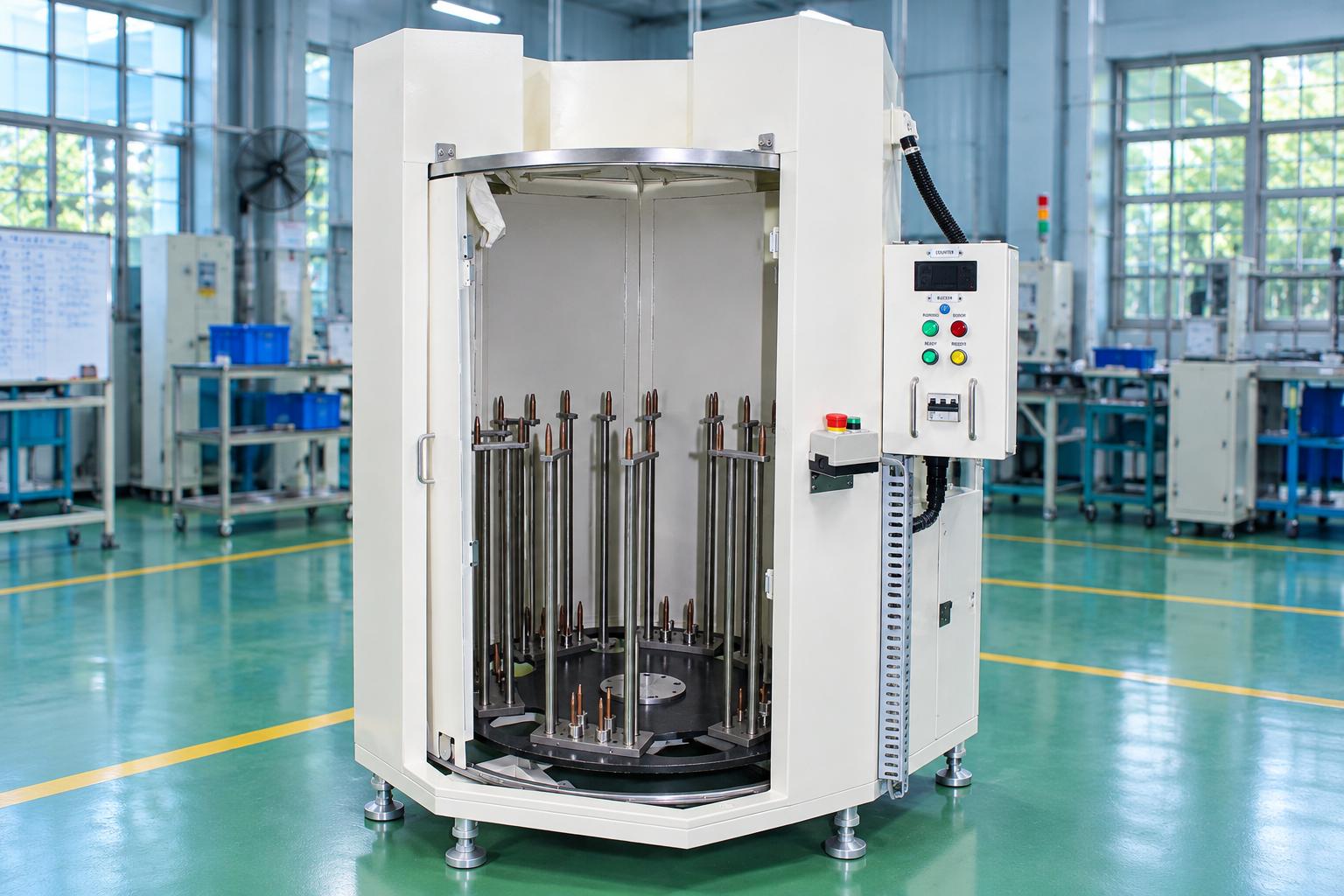
The rotary table component cooling machine positions products on fixtures and moves the assemblies through each processing step. The processing chamber is connected to a cooling source, while the control system manages movement and dwell time. The operator has clearly defined loading and unloading positions, making it convenient to organize the cooling process near the heating area.
The value of this solution lies in coordinating the fixtures, cooling source, and operating cycle with the actual products. Performance should be evaluated based on the component temperature after processing, the ability to meet the requirements of the next production stage, and the operator's working time.
Features of the rotary table configuration
-
Manual loading and unloading: The operator places hot components in the fixture positions, removes cooled products, and initiates the next step.
-
Six fixture assemblies: The rotary table accommodates six assemblies, each with eight product mounting positions according to the reference configuration.
-
Connection to an external chiller: The machine chamber includes a cooling source connection. The mechanical equipment must be coordinated with the station's cooling system.
-
Dwell time management: The timer defines the conditions that must be met before the next step can proceed.
-
Door and machine status monitoring: Push buttons, indicator lights, an alarm buzzer, and a door switch support operation according to the prescribed sequence.
Related structure and technology
The rotary table product cooling machine consists of mechanical assemblies, a cooling chamber, a cold air supply system, and an automatic control system. These components work together to maintain product positioning, control the operating sequence, and support the cooling process according to production requirements.
Rotary table and product fixtures
The rotary table carries fixture assemblies distributed around its center. Mounting posts hold products in their designed orientations, allowing components to be arranged systematically inside the cooling chamber. The fixture assemblies are moved to the operating position by the rotation of the table.
The fixtures must be suitable for the component's shape, dimensions, contact areas, and temperature during loading. The spacing between products should also be considered when arranging the cold air flow. For products that are susceptible to deformation or have surfaces requiring protection, the support method and contact materials must be evaluated under actual thermal conditions.
The number of fixture positions represents the machine's physical configuration. The production output achieved per shift also depends on dwell time, fixture utilization, and loading and unloading operations. When adapting the design for different products, CNC VINA can consider modifying the fixtures and the number of positions according to production requirements.
Rotary mechanism and drive system
The motor, gearbox, pulleys, and belt drive the rotary table. A variable frequency drive (VFD) is included in the configuration to control motor speed. Sensors provide position signals to coordinate movement with the operating sequence.
The rotation cycle must be appropriate for the product weight, fixture retention method, and operator handling time. When selecting the configuration, the stability of the products must be checked during initial rotation, movement between steps, and stopping at the loading and unloading positions. Any increase in rotation speed must be evaluated alongside these conditions.
Cooling chamber and cooling source connection
The machine chamber encloses the product processing area and includes an access door and a connection to an external chiller. According to the proposed configuration, cold air from the chiller is supplied to the component processing area. The tightness of the connections and the arrangement of the airflow must be checked during installation.
When developing the system configuration, the supply air temperature and flow rate, chiller capacity, air distribution within the chamber, and suitable air exhaust path must be determined. These requirements should be evaluated in relation to the heat load of the products introduced during each loading cycle.
If the factory already has a chiller, CNC VINA can assess the connection requirements to coordinate the design. For a new cooling station, the cooling source must be selected together with the machine chamber and fixtures, based on the target component temperature.
Time-based control and door interlocking
The PLC coordinates start commands, sensor signals, door status, and the timer. The operator interface includes push buttons, status indicator lights, and an alarm buzzer. This arrangement helps operators identify whether the machine is ready, running, or requires fault handling.
In the reference configuration, the next operating step can proceed only after the 30-second timer has elapsed. This is the dwell time specified in the operating sequence. The required cooling duration and the component temperature after processing must still be determined through trials using the actual products and cooling source.
The door must remain closed while the machine is operating. If the door opens while the motor is running or during the cooling dwell period, the system stops and generates an alarm. The operator must identify the cause and restore the correct operating conditions before resuming the cycle.
Operating procedure and maintenance of the industrial component cooling system
The industrial component cooling system follows a sequence of preparation, product loading, cooling, component unloading, and transfer to the next production stage. In addition to following the operating cycle, regular inspection and maintenance help maintain the stability of the rotary mechanism, control system, and cooling performance.
Operating procedure for the industrial component cooling system
Step 1: Prepare the cooling station. Inspect the fixtures, rotary mechanism, door, chiller connections, and power supply. Install the machine on a suitable foundation, secure the mounting feet, and prepare the product transfer area from the heating process.
Step 2: Load and unload products. At the designated operating position, the operator places hot components onto the fixtures and removes cooled products according to the procedure. Each component must be positioned correctly to prevent interference with fixed machine parts or adjacent products.
Step 3: Close the door and issue the start command. The system must be in a ready state, with the required position and door conditions satisfied. The operator then issues the command for the rotary table to move to the next position.
Step 4: Cool the products and monitor the dwell time. The products are processed inside the chamber connected to the cooling source. The control system monitors the dwell time before the next step. The cycle coordinates movement with the operating time, while the cooling conditions are established according to the product requirements.
Step 5: Continue the cycle. Once the required conditions are met, the operator proceeds with the next loading and unloading cycle. Product transfer to the subsequent production stage must comply with the agreed temperature and quality criteria.
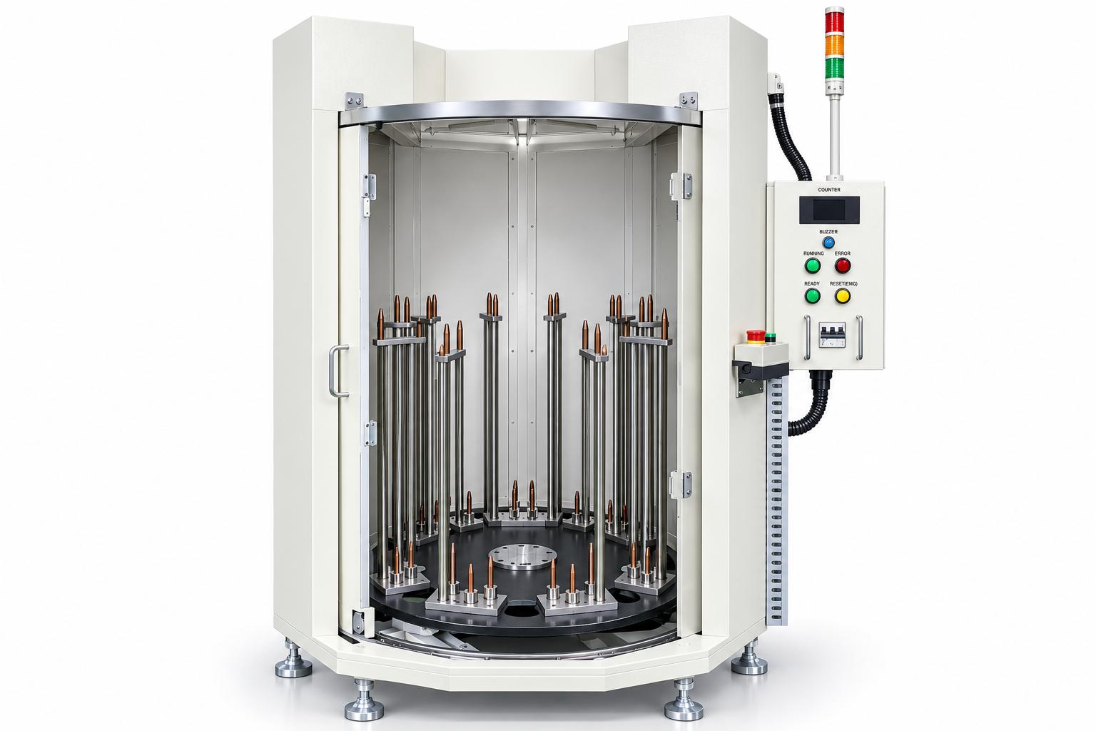
Operation and maintenance of the component cooling machine
Before each shift, inspect the condition of the fixtures, the stability of the mounting posts, rotary table movement, the door, and the cooling source connections. Operators should prepare handling equipment suitable for the product temperature and perform loading and unloading according to the station's operating procedures.
Maintenance points include the belt, pulleys, bearings, rotating shaft, motor, door assembly, and sensors. Monitor unusual noises, excessive play, belt condition, and the stability of the stopping position. The electrical control cabinet, push buttons, and indicator lights should be inspected alongside the mechanical components according to the maintenance schedule.
Drive alignment, jam removal, and any intervention inside the machine chamber must be carried out after stopping the machine and isolating the relevant energy sources. After maintenance, recheck the operating cycle and cooling results before returning the station to production.
Applications in industrial manufacturing
The product cooling chamber can be used in processes that require components to be cooled before inspection, assembly, or transfer to the next production stage. The layout and operating method must be suitable for the product characteristics, temperature requirements, and actual production line conditions.
Cooling components removed from a furnace
The application illustrated in the drawings involves receiving products removed from a furnace, placing them on fixture assemblies, and cooling them using an externally connected cooling source. The machine can be installed near the heating process to organize product flow. Application requires components that are compatible with the fixture orientation, have a defined inlet temperature, and meet specified handover criteria after cooling.
Cooling before inspection or assembly
For processes that require components to be cooled before inspection or assembly, a rotary table cooling station using fixtures can be considered. The objective is to bring the products to a temperature suitable for the receiving process. This solution must be evaluated based on the material, target temperature, and product transfer method. Post-processing inspection criteria should be agreed upon with the production and quality departments.
Cooling long products or components suitable for vertical mounting
The mounting-post configuration suggests a layout suitable for components that can be held vertically. When adapting the machine for long or tubular products, the support structure, contact points, and fixture spacing must be redesigned. Suitability should be determined through sample evaluation and testing, particularly for components requiring deformation control or surface protection.
Organizing cooling operations in a semi-automatic production line
Factories that rely on manual loading and unloading can consider a rotary table station to combine operator handling with controlled movement. The layout must accommodate the distance from the preceding process, operator ergonomics, the quantity of waiting products, and the cycle time of the subsequent process. If a higher level of automation is required, the product feeding and unloading mechanisms can be designed accordingly.
Information buyers need to determine
-
Thermal conditions: Determine the component temperature at the exit of the preceding process, the required final temperature, and the allowable processing time. Appropriate measurement points should be selected to evaluate the thermal condition of the products rather than relying solely on the air temperature inside the chamber.
-
Component characteristics: Provide samples, drawings, weight, and material specifications. Identify permissible fixture contact areas, areas where contact must be avoided, and surface requirements. The component geometry and fixture arrangement affect the accessibility of the cold airflow.
-
Cooling source and installation environment: Determine whether the factory already has a chiller or requires a new one, along with the air supply specifications and connection locations. The installation area must provide sufficient space for handling, product movement, connections, and maintenance.
-
Production volume and handling: Agree on the quantity per loading cycle, dwell time, indexing interval, and operator loading and unloading time. Evaluate the number of products meeting the temperature criteria per shift under defined test conditions.
-
Product changeover: Determine the number of product variants and the range of variations in shape, weight, and inlet temperature. Changing product types may require fixture replacement, layout adjustments, and reevaluation of cooling time.
Trial operation and evaluation before handover
Trial operation should be conducted using products with thermal conditions representative of actual production. Both parties should agree on the measurement method, measurement locations, measurement timing, and acceptance limits before evaluation.
-
Cooling results: Record the component inlet and outlet temperatures. Check representative fixture positions, including those with different levels of access to the cooling source.
-
Product quality: Evaluate surface condition, shape, and the requirements of the subsequent process after cooling.
-
Cycle stability: Check indexing, stopping positions, product retention, and dwell time between operations.
-
Production capability: Run a representative loading quantity and record operator handling, processing time, and the number of products meeting acceptance criteria.
-
Operating conditions: Check the cooling source connections, door signals, emergency stop function, and recovery procedure following an interruption, according to the agreed operating procedure.
The trial results help determine the appropriate cooling source configuration, fixture arrangement, and operating cycle. If the product type, loading quantity, or cooling source conditions change significantly, the relevant acceptance criteria must be reevaluated.
Frequently asked questions
Does the machine require an external chiller?
The proposed configuration includes a connection to an external chiller. When selecting the machine, the chamber, fixtures, drive system, and cooling source requirements must all be considered to ensure that the product cooling requirements are met.
What does the 30-second dwell time mean?
The documentation specifies that the timer must reach 30 seconds before the next operating step. The required dwell time and the resulting temperature reduction must be evaluated using the actual products, cooling source, and selected loading method.
How can operators determine whether a product has cooled sufficiently?
A handover temperature criterion and an agreed measurement method are required. If the process requires automatic product temperature measurement or permits unloading only when a specified temperature threshold is reached, the corresponding sensors and control logic must be included in the design requirements.
Can the fixtures be modified for different products?
CNC VINA can consider designing fixtures for new product samples. The proposed design must be checked for component retention, spacing, loading weight, and cooling conditions. Trial operation is then required to verify the results.
Can loading and unloading be automated?
Additional feeding and unloading mechanisms can be evaluated according to the requirements. The design depends on product geometry, temperature, the transfer method from the preceding process, and the production line's automation level.
The processing chamber is connected to an external chiller. The drive system consists of a motor, gearbox, pulleys, belt, and variable frequency drive (VFD). The controller coordinates position signals, door status, and timing, while indicator lights and an alarm buzzer support operation.
When selecting the machine, businesses should determine the inlet temperature, target handover temperature, component characteristics, loading quantity, and cooling source capacity. Cooling performance is evaluated by measuring product temperatures and inspecting product quality after processing. CNC VINA can design fixtures, the machine chamber, transfer mechanisms, and additional functions according to specific requirements. The final configuration is established through site assessment and trial operation.
What does the 30-second dwell time mean?
The documentation specifies that the timer must reach 30 seconds before the next operating step. The required dwell time and the resulting temperature reduction must be evaluated using the actual products, cooling source, and selected loading method.
How can operators determine whether a product has cooled sufficiently?
A handover temperature criterion and an agreed measurement method are required. If the process requires automatic product temperature measurement or permits unloading only when a specified temperature threshold is reached, the corresponding sensors and control logic must be included in the design requirements.
Can the fixtures be modified for different products?
CNC VINA can consider designing fixtures for new product samples. The proposed design must be checked for component retention, spacing, loading weight, and cooling conditions. Trial operation is then required to verify the results.
Can loading and unloading be automated?
Additional feeding and unloading mechanisms can be evaluated according to the requirements. The design depends on product geometry, temperature, the transfer method from the preceding process, and the production line's automation level.
VIETNAM CNC AND TECHNOLOGY APPLICATION JOINT STOCK COMPANY
Factory: Song Cung Industrial Point, Dong Thap Commune, Dan Phuong District, Hanoi, Vietnam
Telephone: +84 916 63 9355 / +84 915 74 4664
Websites: https://cncvina.com.vn; https://cncvina.net; https://cncviname.com.vn