 Tiếng
Việt
 Tiếng
Anh
 Tiếng
Nhật




 Tiếng Anh


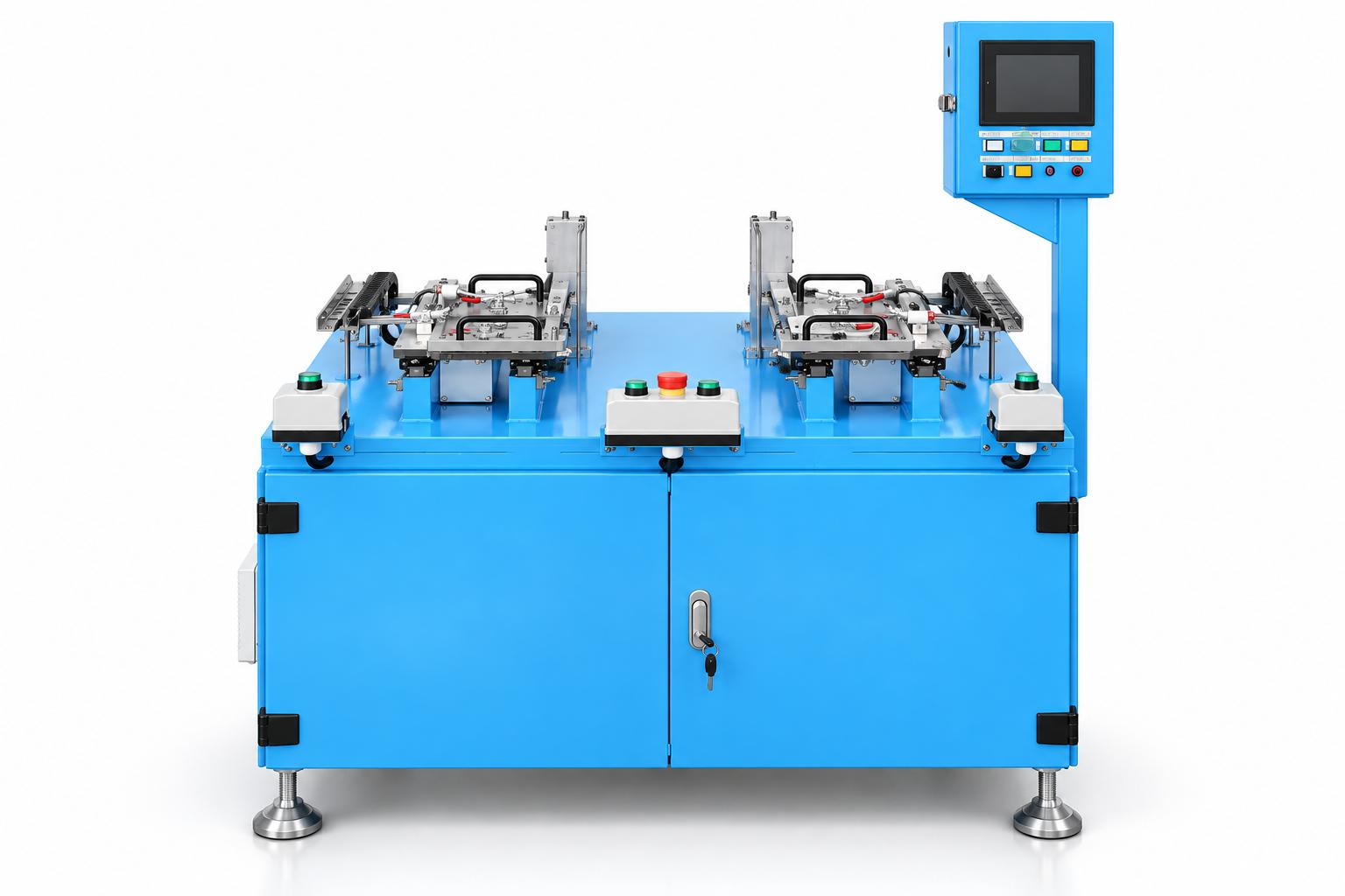
Laser shaft inspection machine
CNC VINA’s laser shaft inspection machine supports in-process product inspection using two workholding stations, a linear motion mechanism, and a non-contact measurement system. The operator selects the product type in the software, loads the part into the fixture, and starts the inspection cycle. The machine moves the part through the measurement position, displays the measurement data on the computer, and determines whether the part passes or fails based on predefined criteria.
The equipment is designed for inspecting shaft-shaped components according to product-specific measurement programs. For diameter or shaft runout measurement, the inspection solution must clearly define the workholding datum, measurement zones, and result calculation method. The manual loading and automatic measurement configuration is suitable for applications that combine operator handling with a controlled measurement sequence, while allowing changes in measurement values to be monitored at different positions along the part.
VIETNAM CNC & TECHNOLOGY APPLICATION JOINT STOCK COMPANY
Hotline: +84.916 63 9355 / +84.915 74 4664
Email: Sales01@cncvina.com.vn / Sales03@cncvina.com.vn
Product description

Custom laser measurement machine is a solution for inspecting the dimensions and geometric characteristics of mechanical components using non-contact measurement technology. The machine is designed to meet the specific production requirements of each business. It uses a laser measuring head combined with a linear motion mechanism to collect position-based data, helping monitor surface variations within the inspection area. Depending on the characteristics of the product, the machine can be designed to measure diameter, shaft runout, or other parameters appropriate to the specified measurement method. The control software allows operators to select measurement programs, display data in tables and graphs, and evaluate pass or fail results based on predefined limits. The machine can be configured with multiple workholding stations, combining manual part loading with an automatic measurement cycle to meet actual operating requirements. Custom-designed locating fixtures, measurement travel, and inspection programs help the system better accommodate the component geometry and the factory's production process. With experience in automation machinery and industrial solutions, CNC VINA provides consultation, design, and manufacturing services for custom laser measurement machines, aiming to improve quality control consistency and optimize inspection processes.
The role of custom laser measurement machines in production quality inspection
For shaft-shaped components, a single measurement value at one position is not sufficient to characterize the entire inspection area. Deviations may occur locally or vary along the measurement length. Collecting position-based data and presenting it in graphical form helps inspectors identify areas of variation and compare them with technical requirements, rather than relying solely on a single summarized result.
The machine can be installed at the post-machining inspection stage or before assembly, depending on the factory's production process. Pass/fail results support decisions on whether parts can proceed to the next stage, whether components require further inspection, and whether feedback should be provided to the production department. The inspection scope must correspond to the characteristics specified in the technical drawing; each measurement cycle evaluates only the criteria included in its program.
For shaft runout measurement, the workholding datum, inspection area, result calculation method, and acceptance limits must be clearly defined when developing the inspection solution. These conditions ensure that the machine's results can be meaningfully compared with the inspection methods currently used in the factory.
Features of the measurement system
-
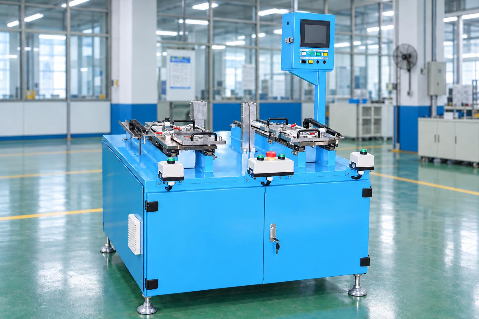
Two workholding stations: Each station has its own start controls and corresponding result display area, making it easier to monitor individual measurement cycles.
-
Non-contact laser measurement: The laser sensors detect changes in surface position as the part moves, minimizing the impact of mechanical contact on the inspection area.
-
Controlled linear motion: The fixture moves through the measurement area at a preset speed, allowing acquired values to be associated with positions along the travel path.
-
Computer-based software: Operators can select the product type, monitor data tables and graphs, evaluate pass/fail results, and count inspection results.
-
Manual part loading: The operator loads and unloads the parts, while the machine performs the motion and measurement cycle once started.
Structure and technology of the non-contact laser measurement machine
The laser measurement machine consists of a locating fixture assembly, laser sensors, a linear motion mechanism, and a control system integrated with data processing software. These components work together to acquire surface data, display measurement results by position, and evaluate deviations against the inspection criteria.
Workholding and part positioning assembly
The fixture holds the part in a suitable position relative to the laser sensors and motion mechanism. Measurement stability depends on how the part rests against the fixture, the cleanliness of the locating surfaces, and the consistency of part placement. Therefore, fixture design is an integral part of the measurement solution and must be considered alongside the component geometry and inspection datum.
When changing products, modifying the measurement program alone may not be sufficient. Parts with different lengths, cross-sections, or datum positions may require a new fixture, adjustments to the sensor positions, or changes to the measurement travel. The selected configuration must ensure that the target area passes through the laser measurement zone while the part remains securely positioned throughout the cycle.
Laser sensors and signal processing unit
The system uses two laser displacement sensors. The measurement technology relies on light reflected from the surface to determine its position within the sensor's operating range. The signals are processed and fed into the measurement program to generate position-based data, calculate results, and compare them against the product's inspection criteria.
The main advantage of non-contact measurement is that the sensors do not need to touch the part during data acquisition. However, signal quality is still affected by surface characteristics, installation conditions, and fixture stability. Surfaces contaminated with oil, highly reflective surfaces, or surfaces with varying colors should be tested using actual production parts before the final configuration is selected.
A sensor's resolution or repeatability alone does not represent the accuracy of the entire system. Final measurement results also depend on the motion mechanism, workholding datum, processing method, and comparison against reference standards. Buyers should evaluate the complete machine using representative parts from their production requirements.
Linear motion mechanism
The drive and linear guide assembly moves the fixture through the measurement position along a predefined travel path. The measurement speed and travel speed outside the measurement zone are configured separately. This distinction allows motion to be adjusted to meet data acquisition requirements while controlling the travel time between positions.
A higher travel speed does not automatically guarantee that measurement requirements will still be met. When selecting the scanning speed, the acquired data and result stability must be verified throughout the measurement area. Productivity calculations should also include loading and unloading time, the return to the starting position, and result processing.
Control system and computer-based measurement software
The controller coordinates motion, measurement signals, and operating status. The computer-based software provides operating modes, product selection, and result displays for both workholding stations. Data tables allow operators to review values by position, while graphs help identify variation trends within the inspection area.
Pass/fail evaluation is based on the criteria configured in the measurement program. Acceptance limits must be derived from the component requirements and the agreed measurement method. Thresholds should not be adjusted simply to reduce the number of rejected parts without first identifying the cause of the deviations.
Operating procedure and usage guidelines for the laser inspection machine
The shaft inspection machine helps automate the inspection of product dimensions, geometry, and accuracy, contributing to greater consistency in quality control. To ensure stable operation and reliable measurement results, operators should follow the correct operating sequence, check the equipment condition, and perform periodic maintenance in accordance with the technical instructions.
Operating sequence of the measurement machine
Step 1: Prepare the system. The operator checks the work area, fixtures, and machine readiness, then returns the mechanism to its home position according to the operating procedure.
Step 2: Select the product to be inspected. Select the product type in the software and verify the corresponding measurement program before starting automatic operation.
Step 3: Load the part into the fixture. Manually load the part, ensuring that it is correctly positioned against the locating surfaces and that the motion path is clear.
Step 4: Start the selected workholding station. Press both start buttons simultaneously at the station being used to initiate the measurement cycle.
Step 5: Move the part and acquire data. The linear mechanism moves the part through the measurement position. The system records the measurement values and displays position-based data in the software.
Step 6: Review the results and unload the part. The operator checks the pass/fail result, removes the part after the cycle is complete, and sorts it according to the factory's inspection procedures.
Both workholding stations should be evaluated as part of the overall operating strategy. The extent to which they improve productivity depends on the control sequence, measurement time, and operator handling time. It should not be assumed that two stations will automatically double production output.
Operation and maintenance
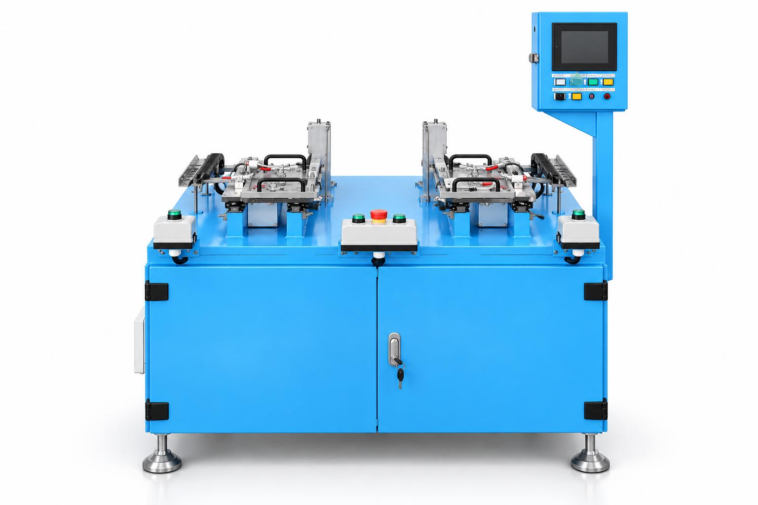
Before each shift, check the cleanliness of the fixtures, the condition of the sensors' viewing areas, and the motion area. Selecting the correct program and performing reference checks according to the factory's procedures help identify changes that may affect measurement results before mass inspection begins.
During operation, monitor the software status, error signals, and any abnormal changes in the graphs. When unusual results occur, investigate the cause according to the technical procedure. Do not ignore warnings or widen the acceptance limits without first verifying the cause.
Cleaning, fixture adjustment, and mechanical maintenance must be performed only after the machine has stopped and the relevant power sources have been isolated according to the established procedure. Never place hands inside the fixture area while the mechanism is moving. After any intervention affecting the measurement process, verify the results before resuming production.
Applications in industrial manufacturing
- Inspection of shaft-shaped components after machining: This is one of the applications most closely aligned with the machine's capabilities. The system acquires position-based data and evaluates results according to a predefined program. For diameter or shaft runout inspection, the measurement method must be validated on the complete machine configuration. When installed after a suitable CNC machining operation, the results can help identify parts requiring further inspection before proceeding to the next production stage.
- Inspection before mechanical assembly: The machine can be integrated into a production line according to specific requirements. For products with critical mating areas, it supports screening based on validated inspection criteria. Successful implementation requires the component geometry, measurement area, and locating datum to be compatible with the laser sensor and fixture configuration. The measurement results do not replace all assembly inspections if the product has additional requirements.
- Manufacturing components for electrical equipment, transmission mechanisms, or the automotive industry: Similar measurement solutions can be considered for shaft-shaped components with compatible inspection requirements. These applications require a design tailored to the specific product and are not automatically supported by every machine configuration. CNC VINA can evaluate adjustments to the fixtures, sensor arrangement, and measurement programs to meet the requirements of each production line.
- Monitoring quality variations during production: The machine also helps technical personnel identify areas requiring further inspection or compare measurement results across samples. Position-based data tables and graphs make it easier to identify variations. For long-term analysis, data storage, part identification codes, and report export requirements must be defined separately within the project scope.
Technical specifications of the laser measurement machine
| Item | Specification |
| Operating mode | Manual part loading and unloading, with an automatic measurement cycle after startup |
| Number of workholding stations | 2 stations |
| Number of sensors | 2 đầu đo dịch chuyển laser |
| Measurement motion | Cơ cấu tuyến tính đưa gá qua vị trí đo |
| Travel speed during measurement | 5 - 20 mm/s |
| Travel speed outside the measurement process | 5 - 300 mm/s |
| Result display | Máy tính, bảng dữ liệu và đồ thị theo vị trí |
| Result evaluation | Đạt hoặc không đạt theo tiêu chí thiết lập, có chức năng đếm kết quả |
| Number of operators | 1 công nhân |
| Working height | 850 ± 50 mm |
The speeds listed above refer to motion speed, not throughput in parts per minute. The product size range, measurement error requirements, and cycle time must be determined based on sample parts, the fixture configuration, and the agreed measurement method.
Information buyers should confirm before selecting a machine
What characteristics need to be measured, and how will the results be used?
The first step is to define the measurement area, the parameters to be inspected, the reference datum, and the acceptance limits specified in the component drawing. It is also necessary to clarify whether the results will be used for in-process sorting, post-machining inspection, or supporting decisions before assembly. Each purpose may require a different measurement arrangement and result display format.
For shaft runout inspection, the datum setup and calculation method should be agreed upon before comparing the results with those obtained using other measurement methods. Even when the same terminology is used, differences in workholding conditions or data acquisition areas can produce results that are difficult to compare.
Sample parts and actual surface conditions
Test samples should represent the range of dimensions, geometries, and surface conditions encountered in production. Testing a single clean and stable part may not fully reflect actual manufacturing conditions. The laser reflection characteristics, repeatability of part positioning, and fixture stability under the intended operating environment should all be considered.
Operating procedures and product changeover requirements
A single operator should be able to load parts, start the machine, review results, and unload components at a pace compatible with the production cycle. Productivity evaluations should account for the entire actual operating cycle, including the handling of parts that fail inspection and require further processing.
If multiple component types are involved, determine which changes require only selecting a different software program and which require fixture replacement or mechanical adjustments. After any change affecting the measurement process, verify the results using reference samples before beginning mass inspection of the new product.
Data requirements and connectivity
The computer-based display supports real-time monitoring of measurement data. If the factory requires historical data storage, file exports, linking results to product identification codes, or transferring data to a management system, these functions should be specified during the design and acceptance planning stages.
Sample testing and system evaluation before handover
Machine acceptance testing should verify measurement quality, pass/fail evaluation, and operating cycle performance using actual production parts. A seemingly stable graph or a display with many decimal places is not sufficient to establish that the machine meets the component's tolerances.
The machine's results should be compared against reference parts or samples with established reference values using an appropriate measurement method. Repeat measurements should then be performed without changing the fixture setup, followed by removing and repositioning the parts to evaluate the effect of handling. Testing both workholding stations helps identify differences that need to be addressed before the system enters production.
Samples known to be acceptable, unacceptable, and close to the acceptance limits should be included in the testing process. The objective is to verify that the evaluation program makes appropriate decisions in critical cases and to confirm that the results are displayed correctly and handled according to the operator's procedures.
The factory may also request additional evaluations of operator-to-operator variation, long-term stability, and measurement performance after product changeovers. The test scope, conditions, and acceptance criteria should be agreed upon before handover. The overall machine accuracy must not be inferred solely from the laser sensor specifications.
Frequently asked questions
Does the machine automatically feed and unload parts?
This configuration requires manual part loading and unloading. The machine automatically performs the motion and measurement cycle after startup. Automatic feeding, unloading, or sorting of accepted and rejected parts can be included as additional design features if required by the project.
Do the laser sensors come into contact with the product?
The sensors acquire measurement signals from light reflected off the surface and do not require mechanical contact with the measurement area. However, the part still contacts the locating fixture, so fixture cleanliness and correct part positioning continue to affect measurement results.
Can measurement accuracy be determined solely from the sensor specifications?
No. The complete machine must be evaluated with its fixtures, motion mechanism, measurement program, and actual samples. The software's display resolution and the sensor's individual repeatability are not equivalent to the measurement error of the entire system.
Will two workholding stations double productivity?
This cannot be concluded from the number of fixtures alone. Productivity depends on measurement time, the operating sequence, and the operator's loading and unloading time. Actual cycle time should be measured using representative products to determine whether the machine can meet production takt time.
Can the machine inspect multiple component types?
A solution can be designed for multiple component types if their measurement ranges and mechanical configurations are compatible. Product changeovers may require fixture replacement, sensor position adjustments, or program modifications. Each component type must be tested and its measurement results validated in the intended configuration.
The CNC VINA laser shaft inspection machine is an important component of assembly and inspection lines, supporting product inspection according to predefined measurement programs and evaluation criteria. The machine features two workholding stations, non-contact laser displacement sensors, and a linear motion mechanism for acquiring position-based measurement data. The operator selects the product type in the software, manually loads the part, and starts the cycle. The machine then performs the movement and measurement process and evaluates the results as pass or fail. Results are displayed on a computer through data tables and graphs, helping operators monitor variations within the inspection area.
The machine can be installed after machining or before assembly when the measurement parameters, fixture datum, and surface conditions are compatible with the system. The measurement range, error limits, and productivity must be validated through sample testing on the complete machine configuration. CNC VINA can provide customized fixture design, measurement programming, and automation levels to help manufacturers develop an inspection process suited to their actual production requirements.