 Tiếng
Việt
Tiếng
Việt
 Tiếng
Anh
Tiếng
Anh
 Tiếng
Nhật
Tiếng
Nhật




 Tiếng Anh

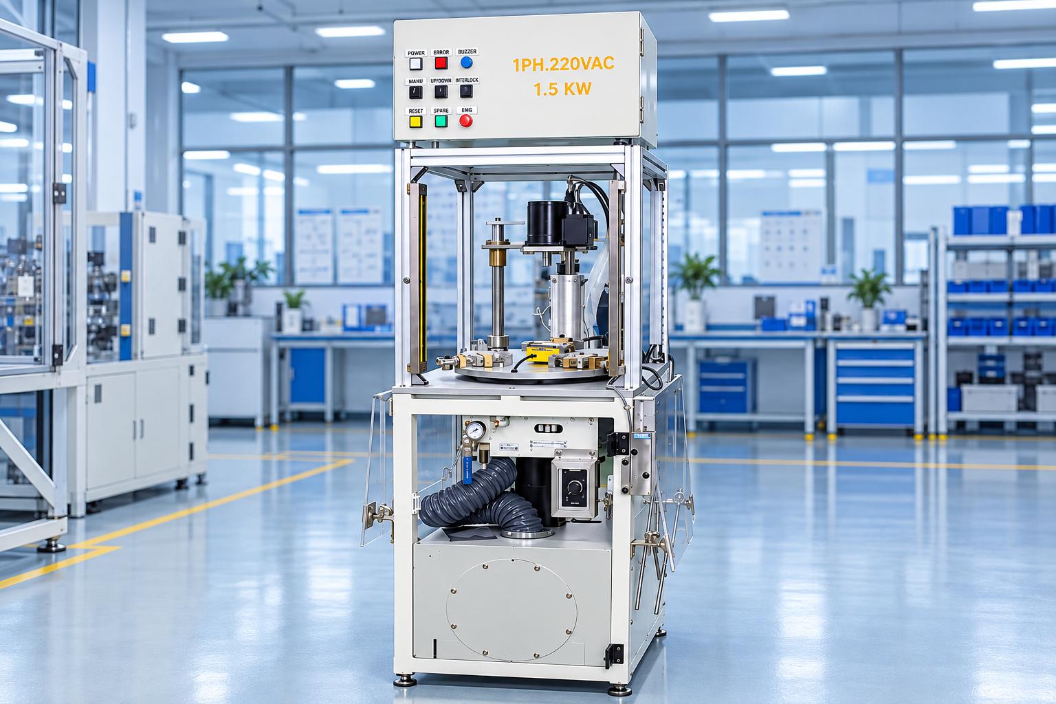
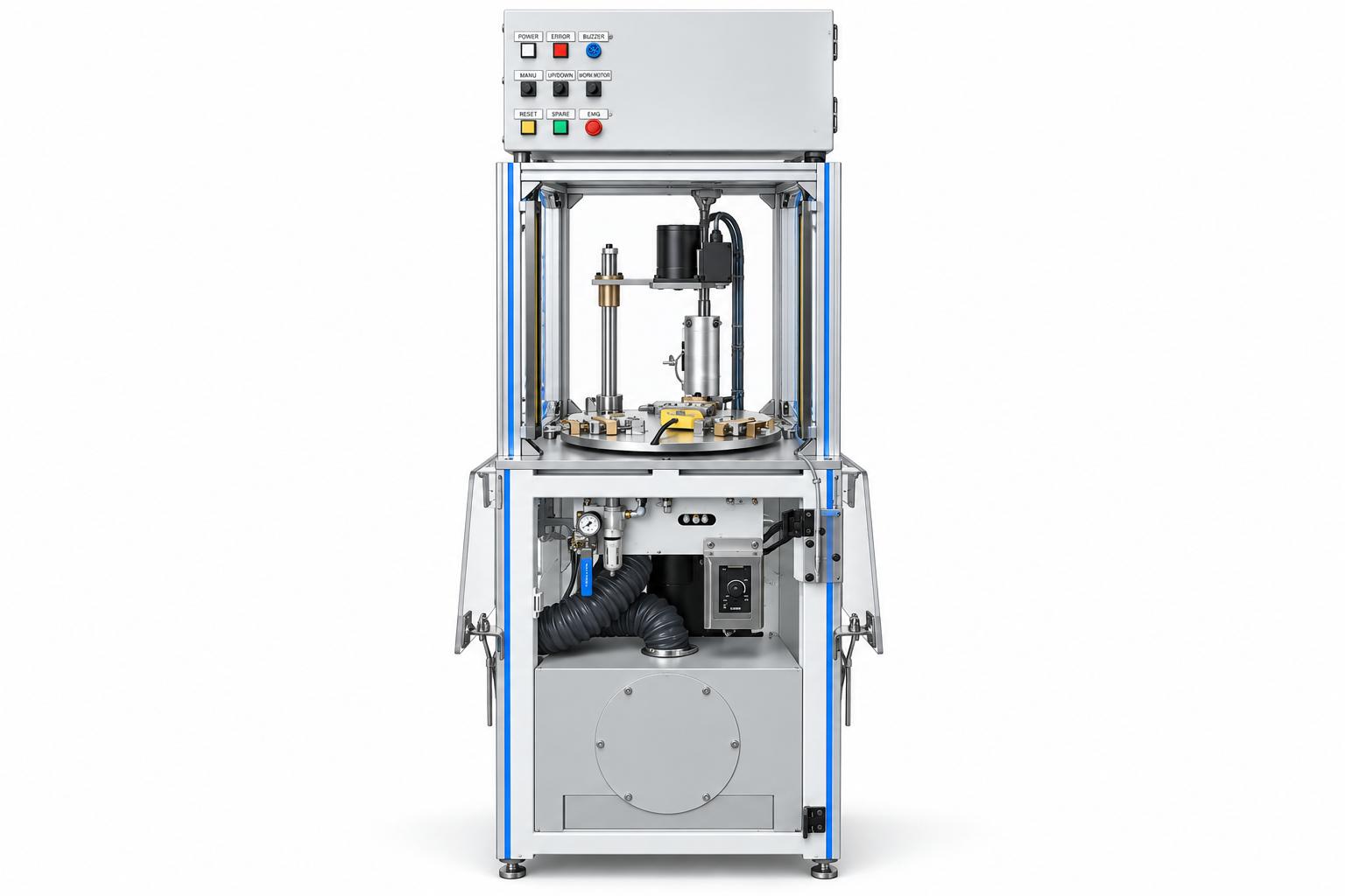
Rotary table deburring machine with wire brush
The CNC VINA deburring machine uses a rotating wire brush to remove burrs in areas where the workpiece comes into contact with the brush. A rotary table moves the fixtured parts into the working position. The machine is suitable for batch finishing processes where manufacturers need to automate repetitive operations and control how the workpieces contact the brush.
In this configuration, the operator loads the parts into the fixtures and activates the machine using a start switch. The machine then indexes the rotary table and lowers the brush assembly according to the operating cycle. Therefore, when selecting the equipment, it is important to evaluate its deburring performance, workpiece fixturing method, and the operator’s loading and unloading time.
VIETNAM CNC & TECHNOLOGY APPLICATION JOINT STOCK COMPANY
Hotline: +84.916 63 9355 / +84.915 74 4664
Email: Sales01@cncvina.com.vn / Sales03@cncvina.com.vn
Product description

The CNC VINA deburring machine is designed to remove burrs and finish parts in industrial manufacturing processes. It uses a rotating wire brush to remove excess material from suitable contact areas on the workpiece. Combined with a rotary table and positioning fixtures, the machine moves parts into the working position according to a preset cycle. This solution is suitable for batch finishing operations, helping mechanize repetitive tasks and improve consistency during processing. During operation, the operator places the parts into the fixtures and starts the machine. The system then automatically indexes the rotary table and lowers the brush assembly to perform the deburring operation. Processing results depend on the workpiece material, burr characteristics, brush type, and fixturing method. So, what should manufacturers consider when selecting a deburring machine for their production line? In this article, let’s explore these factors with CNC VINA.
The role of deburring machines in manufacturing
Burrs are excess material remaining along edges or in areas that have undergone machining. Deburring helps prepare parts for inspection and subsequent manufacturing operations. Practical requirements may include removing sharp edges, cleaning contact areas for assembly, or removing excess material from specific locations. Each requirement needs to be evaluated separately.
A deburring machine provides a defined working position for the workpiece, eliminating the need for operators to continuously hold and guide parts toward a tool by hand. Fixtures maintain the correct workpiece position, the rotary table moves the parts into the processing area, and the brush assembly performs the deburring operation. The benefits should be verified through machine trials, particularly in terms of consistency across parts and the ability to preserve surfaces that must remain unaffected.
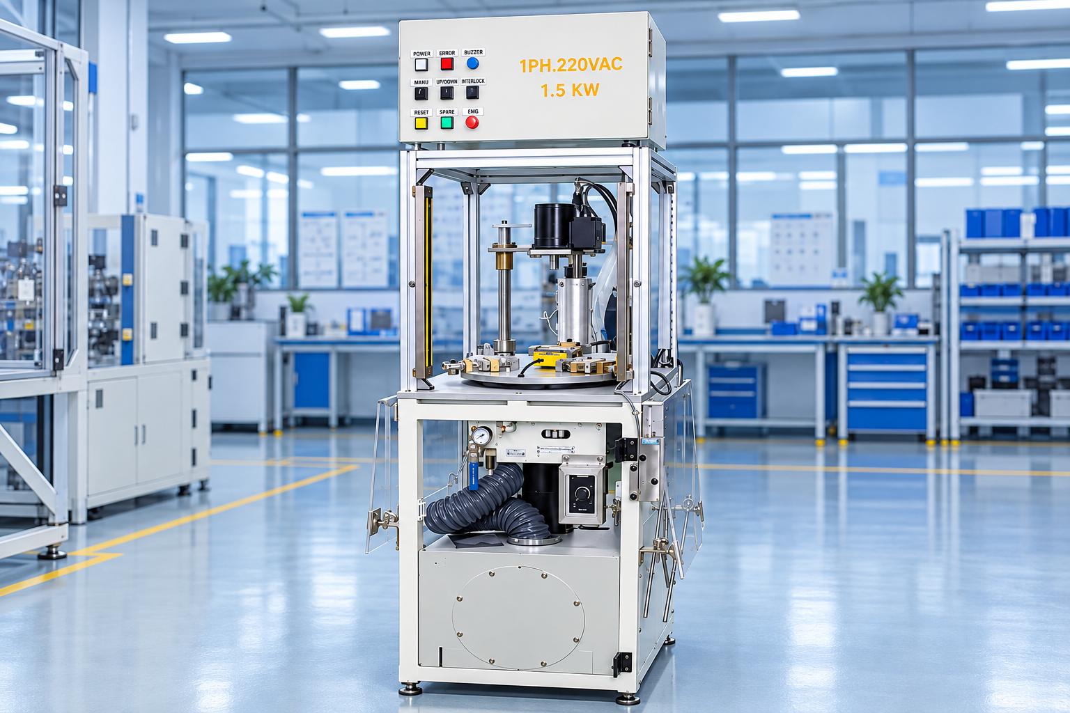
Features of the rotary table configuration
-
Three fixtures positioned 120 degrees apart: provide workpiece-holding positions on the rotary table and move the parts into the brush working area.
-
Separate brush rotation and rotary table motors: drive two distinct movements during the deburring process.
-
Pneumatic cylinder for brush assembly lifting and lowering: moves the entire brush and motor assembly up and down along the guide system.
-
Quick-change brush mechanism with a locking pin: simplifies tool replacement when the brush wears out or processing requirements change.
-
Position sensor and area sensor: monitor movement status and detect intrusions into the monitored area.
-
Dust extraction unit and foldable auxiliary tables: help collect dust generated during processing and organize workpieces in the operating area.
Machine structure and related technologies
The rotary table deburring machine with a wire brush consists of mechanical components, processing tools, and a control system that work together to remove burrs. Each component performs a specific function, from positioning workpieces and generating brushing motion to lifting, lowering, and monitoring machine operation. In addition, the dust collection system and work area layout support operation, cleaning, and equipment maintenance.
Rotating wire brush and deburring mechanism
The motor drives the brush assembly in rotation. When the tool contacts the area requiring treatment, the brush bristles mechanically act on the burrs. The term “deburring machine” in this context refers to a machine that removes burrs using a rotating brush; the configuration described uses a brush assembly rather than a cutting tool that follows a specific profile.
In brush-based processing, the bristle material, tool shape, and degree of contact with the workpiece affect the results. Metal wire brushes and abrasive filament brushes are two different options that should be tested according to the workpiece material and burr characteristics. The same brush should not be used for every application simply because it fits the machine.
For large, firmly attached, or difficult-to-reach burrs, the capability of the brushing method should be evaluated before selecting the configuration. If the requirement is to produce a chamfer with specified dimensions, an appropriate cutting or grinding process and separate measurement criteria should be considered. Burr removal and producing a chamfer to drawing specifications are two different requirements that must be clarified from the outset.
Rotary table and positioning fixtures
The rotary table carries three fixture assemblies. Each fixture positions and holds the workpiece in the required orientation so that the burr area is correctly aligned with the brush. The clamping mechanism uses cam rollers and springs, while the fixture contact surfaces are designed according to the workpiece geometry.
The cleanliness of the locating surfaces and the condition of the clamping mechanism directly affect the working position. If a workpiece is misaligned or the fixture has excessive play, the brush may make different levels of contact during successive cycles. When changing workpiece models, check the locating references, clamping stability, and clearance from surrounding mechanisms.
Pneumatic lifting and lowering assembly
The cylinder moves the motor and brush assembly up and down. Guide shafts and linear bushings maintain the direction of movement, helping the assembly move steadily during operation. The air supply lines, cylinder condition, and position confirmation signals should be checked when installing or adjusting the machine.
Compressed air is used to drive the lifting and lowering movement. The air supply pressure cannot be used as a substitute for the actual contact force between the brush and the workpiece. The degree of contact also depends on the mechanism, working position, and selected tool.
Control system and status monitoring
The control panel includes push buttons, a manual/automatic mode selector, a power indicator, an error indicator, and an emergency stop button. Manual mode allows authorized personnel to check the lifting and lowering movements and individual motors during adjustment, in accordance with the prescribed procedure.
The system includes a sensor that monitors the rotational position of the fixture assembly and an area sensor. If a fault occurs or an intrusion into the monitored area is detected during movement, the machine stops and indicates an error. These functions must be tested together with the actual guarding arrangement during equipment acceptance.
Dust collection and work area layout
The dust extraction unit connects to an extraction hose to help collect dust generated during brushing. When selecting an extraction solution, evaluate the type of dust or burr fragments produced, the extraction point, and the cleaning method for the collection components. These factors also affect how the machine should be positioned in the workshop.
Two auxiliary tables can be folded up or down to help organize workpieces in the operating area. In addition to the machine's overall dimensions, the required floor space should include room for workpiece placement, loading and unloading, door opening, and maintenance.
Operating principle of the deburring machine
The rotary table deburring machine with a wire brush operates through an automatic cycle that combines workpiece positioning on the rotary table with a rotating brush assembly to remove burrs from designated areas. The operating sequence includes workpiece loading, machine startup, indexing to the processing position, and lowering the brush assembly to perform the operation. To maintain processing quality and stable operation, the prescribed operating procedures, equipment inspections, and regular maintenance must be followed.
Operating procedure for the wire brush deburring machine
Before starting, the machine must be supplied with power and compressed air and initialized to its home position. The home-position indicator lets the operator know that the system is ready to switch to automatic mode.
Step 1: Load the workpiece into the fixture. The operator places the part against the locating references at the loading position and checks its orientation and clamping condition.
Step 2: Start the cycle. Once the operator has moved clear of the moving area and all readiness conditions have been met, the operator activates the start switch.
Step 3: Move the workpiece to the brush station. The rotary table motor indexes the fixtured workpiece to the processing position.
Step 4: Lower the brush assembly. The cylinder lowers the brush and motor assembly. The rotating brush then removes burrs from the contact area.
Step 5: Load and unload when permitted. Remove the finished workpiece and load the next part at the operating station when the machine is in the permitted state, in accordance with the operating procedure.
Productivity must be verified based on the actual processing time and workpiece loading and unloading cycle.
Operating and maintenance considerations for the deburring machine
Before each shift, check the condition of the fixtures and brush, the work area, the air supply, and the status indicators. Load or unload workpieces only when the machine is in the permitted state. Never reach into the brush area, rotary table, or lifting mechanism while they are moving.
Maintenance points include guide shafts and bushings, bearings, clamping mechanisms, motors, cylinders, sensors, and the dust extraction unit. Worn or damaged brushes must be handled according to the agreed replacement criteria, as changing the tool may affect the results on the workpiece.
If vibration, unusual noise, unstable movement, or an error indication occurs, stop the machine and investigate the cause before restarting it. Cleaning, brush replacement, adjustment, and repair must be performed after the machine has stopped and its energy sources have been isolated in accordance with the appropriate procedure, and only by authorized personnel.
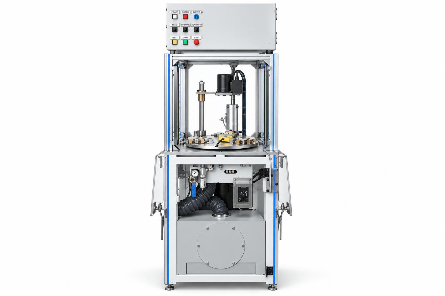
Industrial manufacturing applications
-
Batch finishing of manufactured parts: The rotary table configuration is suitable for consideration when processing parts with a defined fixturing orientation and burr areas accessible to the brush. The machine handles indexing and brushing operations, while the operator loads the workpieces. Application requires fixtures that hold the parts securely and a tool that meets the required output standards through sample testing.
-
Machining of mechanical components: Manufacturers can consider a customized machine configuration for removing burrs after cutting, drilling, or milling in areas suitable for brush access. The equipment helps prepare edges and contact surfaces before inspection or assembly. The tool type, approach direction, and degree of contact should be selected according to the material, burr dimensions, and surfaces that must be protected.
-
Manufacturing of plastic parts and molded products: For thin excess material in accessible areas, a brushing solution with dedicated fixtures can be tested. Scratches, deformation, and the degree of edge rounding should be inspected after processing. Thick excess material, deep parting lines, or hidden areas may require a different technology. Suitability must be evaluated using actual workpiece samples.
-
Electronic components, home appliances, and automotive auxiliary parts: In these industries, deburring can help meet assembly requirements and protect contacting components. CNC VINA can consider designing fixtures, tools, and loading and unloading arrangements to suit individual components. The processing scope, cleanliness requirements, and inspection standards should be agreed upon for each project.
Technical specifications of the rotary table wire brush deburring machine
| Item | Specifications |
| Processing method | Rotating wire brush combined with a rotary table carrying fixtures |
| Fixture arrangement | 3 assemblies positioned 120° apart around the rotary table center |
| Operating personnel in the design | 1 operator to load workpieces and start the cycle |
| Reference cycle time in the design | 6 seconds per part; to be verified under actual sample and operating conditions |
| Main power supply | Single-phase AC 220 V |
| Required power | 1.5 kW |
| Control voltage | DC 24V |
| Lifting and lowering mechanism | Pneumatic cylinder combined with guide shafts and bushings |
| Control modes | Manual and automatic |
| Brush replacement | Quick-change mechanism with a locking pin |
| Dust collection | Dust extraction unit and extraction hose |
Note: The specifications above describe a reference configuration. For different workpieces, the machine dimensions, fixtures, tools, and cycle time are determined according to the processing requirements. The required power rating does not represent a fixed level of electricity consumption under all operating modes.
Factors to clarify when selecting a machine
-
Burr location and type: Mark the areas requiring treatment on the sample or drawing, and identify the burrs to be removed and the surfaces that must not be affected. A part with multiple treatment areas may require a different fixturing orientation or tooling solution.
-
Workpiece material and geometry: Thin parts, areas prone to deformation, and finished surfaces require separate evaluation. The fixture must hold the workpiece in the correct position without damaging it, while the brush must be able to reach the required area within the available working space.
-
Post-processing quality standards: Agree on how to verify residual burrs, edge condition, scratches, and critical dimensions. If surface roughness, edge radius, or cleanliness must be measured, define the inspection method and acceptance limits before machine trials.
-
Product changeover and operating costs: Evaluate whether locating references can be shared, how long fixture and brush changes take, and how the working position will be revalidated. Cost calculations should include consumable tools, cleaning, replacement time, and the number of parts that pass inspection.
Sample testing and evaluation before handover
Testing should use workpieces representative of actual production conditions, including samples with typical burrs and more challenging burrs. Results should be inspected across all required areas, not just the areas that are easiest to see.
-
Part quality: Residual burrs, edge condition after processing, scratches or deformation, and dimensions that must be preserved.
-
Fixture stability: The ability to position parts correctly and maintain consistent results across the three fixture positions on the rotary table.
-
Operating cycle: Workpiece loading and unloading time, machine cycle time, and the number of acceptable parts produced during an agreed test period.
-
Tool condition and dust collection: Brush wear trends, changes in results over time, residual dust, and ease of cleaning.
-
Control functions: Homing, position confirmation, error indication, emergency stop, and the response of the area sensor.
The 6-second cycle time per part is a reference value from the design. When planning production, confirm which operations are included in this time and measure it again using actual workpieces before using it to calculate production capacity.
Frequently asked questions
Does the machine automatically load and unload workpieces?
The configuration described uses one operator to load the workpiece and activate the start switch. The processing movements are then carried out according to the programmed cycle. If automatic loading and unloading are required, CNC VINA can consider additional design solutions based on the workpiece geometry and integration with adjacent processes.
Can the machine process different products simply by changing the brush?
Changing the brush is only one part of a product changeover. The fixtures, locating references, contact areas, lifting and lowering stroke, and clearances during rotary table movement must also be checked. Whether the same configuration can be shared must be confirmed through sample testing.
Can the machine remove all types of burrs?
Processing capability depends on burr adhesion, accessibility, and workpiece material. For very deep areas, large excess material, or applications requiring an edge with specific dimensions, alternative technologies and tools should be evaluated. Actual workpiece samples provide the basis for selecting a suitable solution.
Do three fixtures mean that three parts are processed simultaneously?
The three fixtures provide three workpiece positions on the rotary table. The number of fixture positions does not, by itself, determine how many parts are processed simultaneously or the overall production capacity. The coordination of the positions within the operating cycle and the actual loading and unloading rate must be evaluated.
The CNC VINA deburring machine is designed to help automate finishing operations using a rotating wire brush combined with a rotary table and positioning fixtures. The system helps control the contact orientation between the brush and workpiece, contributing to more consistent deburring results. With three fixture assemblies, a pneumatic lifting and lowering mechanism, and a flexible control system, the machine is suitable for batch machining processes that require stable workpiece positioning. In addition, the quick-change brush mechanism and dust extraction system support machine operation, cleaning, and maintenance. To achieve optimal results, manufacturers should select tools that suit the workpiece material, burr geometry, and product quality standards. Testing actual workpiece samples helps evaluate post-processing quality, fixture stability, and production cycle time before the machine is put into service. CNC VINA provides consultation, design, and manufacturing services for customized deburring machines to meet the workpiece characteristics and automation requirements of individual manufacturers.