 Tiếng
Việt
Tiếng
Việt
 Tiếng
Anh
Tiếng
Anh
 Tiếng
Nhật
Tiếng
Nhật



 Tiếng Anh

3-axis robot XYZ robot is a specialized robot with high precision and speed, used in the manufacturing and assembly of electronic components, cars and motorbikes, such as applying glue to PCB circuits. , apply grease, apply glue to multi-point positions, difficult to manipulate, complex profiles on motorbike gearboxes, circuit boards... The first 3-axis robot product designed and launched by CNCVina in 2012 has been rated marks CNC-VINA's technology mastery in the industrial robot market. With the strong development of technology over the past 10 years, CNCVina always updates the latest solutions and advances in the region and the world on 3-axis robots in particular and robot systems to apply to serve, Improve customer's production system.
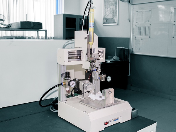
3-axis robot: Technology solution for the manufacturing industry
VIETNAM CNC & TECHNOLOGY APPLICATION JOINT STOCK COMPANY
Hotline: +84.916 63 9355 / +84.915 74 4664
Email: Sales01@cncvina.com.vn / Sales03@cncvina.com.vn
Product description

3-axis robot is an automation system that uses three independent linear axes along the X, Y, and Z directions to position the end effector within the working space. With its linear motion structure, the robot can perform operations such as picking, placing, workpiece feeding, assembly, inspection, and product handling according to a programmed sequence. Compared with robotic systems with more degrees of freedom, a 3-axis robot has a relatively simple structure and is well suited to processes that require repetitive movements to predefined coordinates. Depending on requirements for payload, speed, stroke, and product characteristics, the system can be designed with suitable dimensions and actuation mechanisms for each production line. CNC VINA develops and integrates 3-axis robots based on the specific requirements of each automation application, with the option to integrate workpiece feeding systems, conveyors, sensors, and end effectors as required. In the following article, let’s explore the structure, operating principle, advantages, limitations, and common applications of 3-axis robots in manufacturing with CNC VINA.
Characteristics and capabilities of 3-axis robots
A 3-axis robot is designed with three independent linear axes along the X, Y, and Z directions. The three axes work together to determine the position of the end effector within the working space, allowing the robot to perform programmed operations based on predefined coordinates. With this linear motion structure, the robot can handle a range of tasks such as pick-and-place, workpiece feeding, product handling, assembly, inspection, and machine loading/unloading. The system can be configured with suitable strokes, payload capacities, and end effectors to meet the requirements of each production line.
Components and functions of a 3-axis robot
A 3-axis robot is an industrial robotic system with three degrees of freedom, allowing the end effector to move along the X, Y, and Z axes within the working space. These movements are coordinated through the mechanical structure, drive system, and controller to perform operations according to the programmed sequence. Depending on the specific application, the robot can be integrated with appropriate components and peripheral equipment.
Mechanical arm
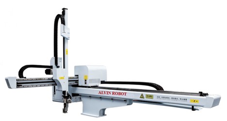
The mechanical arm is the mechanical structure responsible for generating movement and positioning the end effector at the required location within the working space. In a 3-axis robot, this structure is designed to provide movement along the X, Y, and Z axes through the corresponding linear guidance and drive mechanisms. Depending on the configuration, the mechanical arm can be designed with different dimensions, strokes, and payload capacities to meet specific production requirements.
End effector
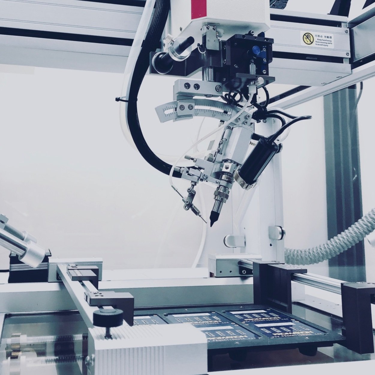
The end effector is the component mounted at the end of the mechanical arm and is responsible for directly performing the required operation on the product or workpiece. Depending on the application, a 3-axis robot can be equipped with various types of end effectors, such as grippers, vacuum suction tools, welding heads, drilling heads, cutting tools, or other specialized mechanisms. The selection of an appropriate end effector should be based on the product’s shape, dimensions, weight, and characteristics.
Drive system
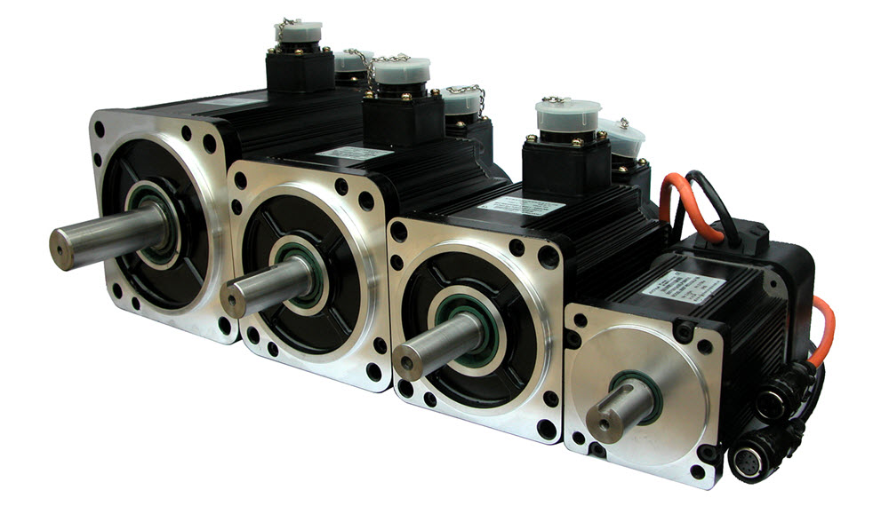
The drive system is responsible for generating and transmitting motion to the robot’s axes based on signals from the controller. Depending on the configuration, the system may use servo motors, stepper motors, and suitable transmission mechanisms to meet requirements for speed, payload, and positioning accuracy. The drive system works together with the linear guidance system and mechanical components to ensure stable robot movement along the programmed trajectory.
Controller
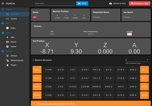
The controller is responsible for receiving the operating program and coordinating the robot’s movements according to the predefined coordinates. It can receive feedback signals from sensors, process operating conditions, and send commands to the drive system to execute the automated cycle. Depending on the system design, the control system can be connected to machines, conveyors, workpiece feeding equipment, and other peripheral devices within the production line.
Sensors
Sensors provide feedback signals that enable the system to determine the robot’s position and status, as well as the condition of the product during operation. Depending on the application requirements, a 3-axis robot can be integrated with limit switches, position sensors, product detection sensors, or other measurement and inspection devices. When combined with a vision system or suitable inspection equipment, the robot can perform positioning, inspection, and product handling operations according to the requirements of the production line.
Operating principle
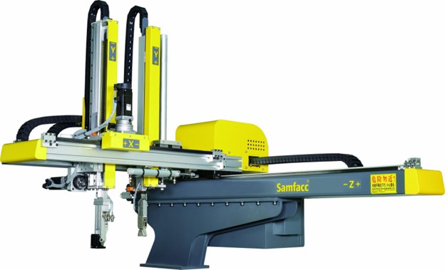
A 3-axis robot is a Cartesian robot that uses three linear axes, X, Y, and Z, to position the end effector at designated locations within the working space. When an operating program is received, the controller processes the coordinates and motion sequence, then sends signals to the drive system of each axis. The drive mechanisms work together with the linear guidance system to generate linear motion along each axis, positioning the end effector at the required location. During operation, sensor signals can be used to monitor the robot’s position, motion status, and operating conditions.
X-axis
The X-axis generates linear motion along the X direction and moves the end effector within its designed stroke range. Depending on the robot configuration, movement along the X-axis may correspond to the horizontal or longitudinal direction of the machine. This axis works in coordination with the other axes to position the end effector at the required coordinates within the working space.
Y-axis
The Y-axis generates linear motion along the Y direction, allowing the end effector to move along the corresponding direction within the working plane. When combined with the X-axis, the robot can access different positions within the working area according to the programmed coordinates.
Z-axis
The Z-axis generates linear motion along the Z direction and is typically used to move the end effector upward or downward, depending on the robot configuration. Combined with the X and Y axes, the Z-axis enables the robot to perform operations such as pick-and-place, workpiece feeding, assembly, or product handling between positions at different heights.
Coordination of the three axes
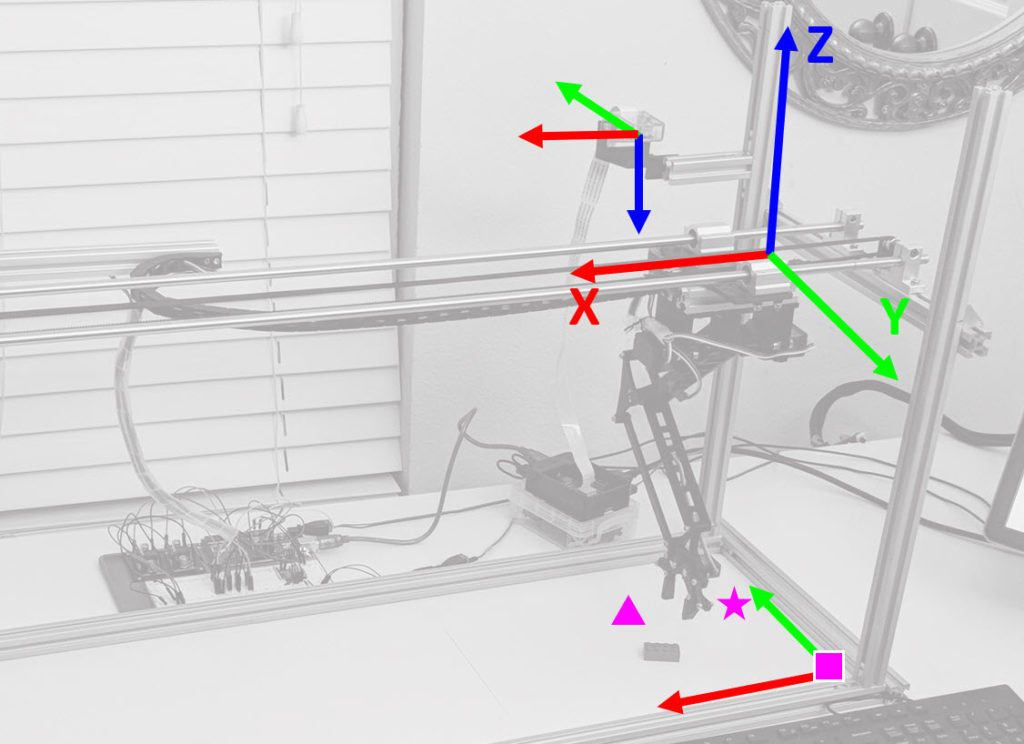
The X, Y, and Z axes operate according to the control program to determine the position and motion trajectory of the end effector. When the robot needs to move to a specific location, the controller coordinates the movement of the axes sequentially or simultaneously, depending on the program and process requirements. This enables the robot to perform repetitive cycles such as picking and placing products, feeding workpieces into machines, material handling, assembly, and inspection within its designated working range.
Key features of CNC VINA’s 3-axis XYZ robots
CNC VINA’s 3-axis XYZ robots are designed according to the requirements of each process and production line, with control programs that can be configured to suit actual operating procedures. The system supports multiple operating modes, allowing engineers to configure and test programs before the robot is put into the production cycle. For systems configured to support G-code, operators can enter commands, test individual lines on a computer, and run the program in a test mode before operating the robot. Once completed, the program can be stored in the system memory for use in subsequent production cycles. This approach facilitates program testing, adjustment, and management when products or process requirements change.
The robot can be designed with dimensions, strokes, payload capacities, and end effectors suitable for each application. Depending on the production line requirements, CNC VINA can integrate the robot with machining equipment, conveyors, workpiece feeding systems, inspection systems, and other automation equipment. In addition to 3-axis robots, CNC VINA develops and integrates various automation solutions, including welding robots, Robocar – AGV autonomous vehicles, and integrated robotic automation lines. The appropriate robot configuration and automation equipment are selected based on the product requirements, production capacity, installation space, and process conditions of each factory.
Applications of 3-axis robots
Assembly and material handling lines
A 3-axis robot can be used to pick, move, and place products or workpieces between different positions on a production line. It can also perform operations such as workpiece feeding, unloading products from machines, transferring components to the next process, and assembling components that require coordinate-based movement. For material handling applications, the end effector can be selected according to the characteristics of the product, such as mechanical grippers, vacuum suction tools, or specialized gripping mechanisms. For products with large dimensions or high weight, the robot configuration must be appropriately designed in terms of payload capacity, stroke, and mechanical structure.
Welding and machining along fixed trajectories
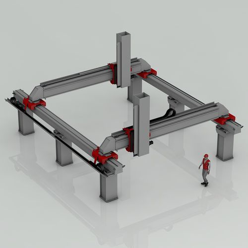
A 3-axis robot can be integrated with a welding head or machining equipment for applications involving relatively simple motion paths and requiring limited changes in tool orientation. The robot can move the end effector along a programmed trajectory to perform repetitive operations at predefined positions. For welding or machining processes that require simultaneous control of the end effector’s position and orientation, a robot with more degrees of freedom may be required, depending on the specific process requirements.
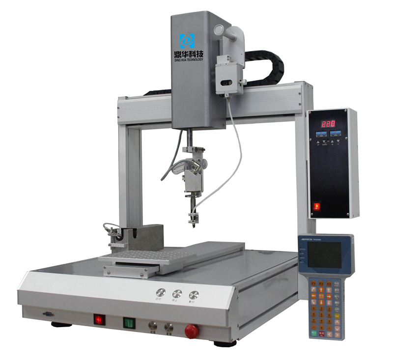
Paint
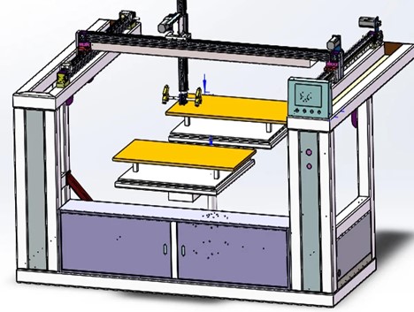
A 3-axis robot can be used in certain spraying or coating systems where the spray path and nozzle position are predefined. Movement along the three axes allows the spray nozzle to cover the required processing area according to the programmed sequence. For products with complex geometries or applications requiring continuous changes in spray orientation, an additional rotary mechanism or a robot with more degrees of freedom may be required to meet the process requirements.
Pallet loading and unloading
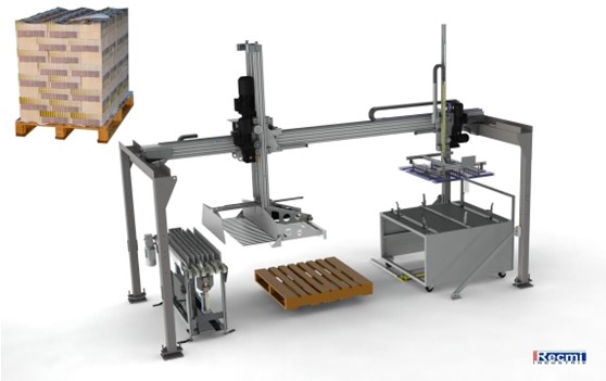
A 3-axis robot can perform coordinate-based pick-and-place operations, such as transferring products between conveyors, trays, pallets, or production areas. When equipped with a suitable gripper, the robot can carry out programmed product loading or unloading sequences. Practical applicability depends on the payload, product dimensions, cycle time, robot stroke, and product arrangement requirements.
Inspection/testing
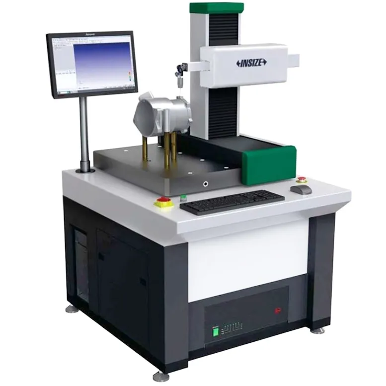
A 3-axis robot can be integrated with cameras, sensors, or measuring devices to position products for inspection or move measuring tools according to predefined coordinates. Depending on the system configuration, the robot can support operations such as dimensional inspection, position detection, visual defect detection, or measurement of certain product parameters. Combining the robot with a machine vision system or specialized measuring equipment allows inspection processes to be performed automatically and repeatedly. In general, 3-axis robots are suitable for applications requiring linear movement and coordinate-based positioning, particularly pick-and-place, workpiece feeding, material handling, machine loading/unloading, assembly, and inspection. For applications requiring complex changes in end-effector orientation or operations involving multiple poses, a robot configuration with a suitable number of degrees of freedom should be considered.
Comparison of 3-axis robots with other industrial robots
A 3-axis robot is not a direct replacement for every type of industrial robot. Depending on requirements for motion trajectory, speed, payload, working space, and end-effector orientation, different robot configurations can be considered.
6-axis robots
A 6-axis robot has six degrees of freedom, allowing it to change the position of the end effector in space while also adjusting its orientation into different poses. Unlike a 3-axis robot, which primarily generates linear movement along the X, Y, and Z axes, a 6-axis robot also provides rotational movements for more complex trajectories and end-effector orientation. 6-axis robots are commonly used in applications such as welding, pick-and-place, assembly, machining, painting, and handling products with complex geometries. Selecting a 6-axis robot instead of a 3-axis robot depends on the specific requirements for degrees of freedom and end-effector orientation.
SCARA robots
A SCARA (Selective Compliance Assembly Robot Arm) typically has four degrees of freedom, including movement in the X-Y plane, movement along the Z-axis, and rotation around the Z-axis. This configuration is suitable for pick-and-place, assembly, component feeding, and product positioning applications with relatively fixed motion paths. Compared with a 3-axis Cartesian robot, a SCARA robot can provide rotational movement of the end effector, while a 3-axis robot offers direct linear movement along the X, Y, and Z axes. The selection between these two robot types should be based on the motion trajectory, working space, and operational requirements of each process.
Delta robots
A Delta robot uses a parallel kinematic mechanism with multiple linkages arranged in a symmetrical configuration to generate movement of the end effector. A common Delta robot configuration has three translational degrees of freedom, while some versions can be equipped with additional rotational capability depending on the design.
Delta robots are commonly used for pick-and-place applications requiring short cycle times, particularly in the food, pharmaceutical, electronics, and packaging industries. Unlike a 3-axis Cartesian robot, a Delta robot uses a parallel mechanism rather than linear axes arranged along the X, Y, and Z directions. The selection of a 3-axis robot, SCARA robot, Delta robot, or 6-axis robot should be based on the actual requirements of the production line, including motion trajectory, payload, cycle time, working range, accuracy, and end-effector orientation.
VIETNAM APPLICATION TECHNOLOGY & CNC JOINT STOCK COMPANY
Factory: Song Cung Industrial Cluster, Dong Thap Commune, Dan Phuong District, Hanoi, Vietnam
Office: Rox Tower Building (Rox Center Goldmark City), No. 136 Ho Tung Mau Street, Bac Tu Liem District, Hanoi, Vietnam
Phone: +84.916 63 9355 / +84.915 74 4664
Website: https://cncvina.com.vn; https://cncvina.net; https://cncviname.com.vn