 Tiếng
Việt
 Tiếng
Anh
 Tiếng
Nhật




 Tiếng Anh

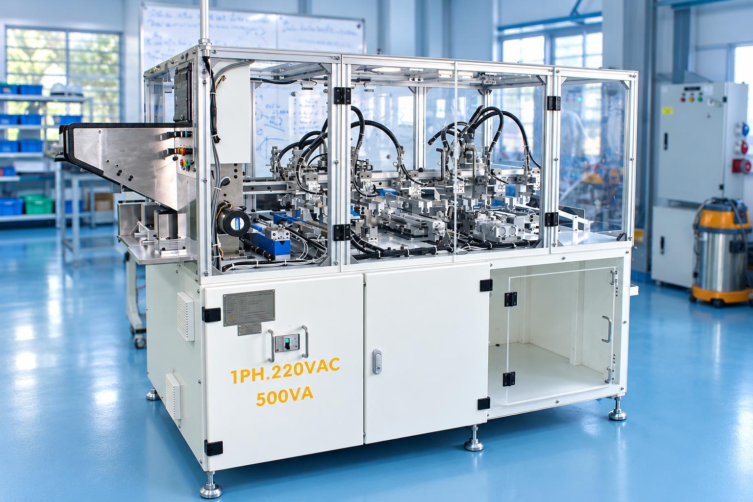
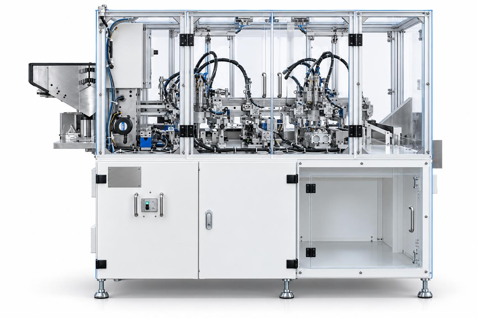
Automatic stainless steel shaft insertion and rubber cutting machine
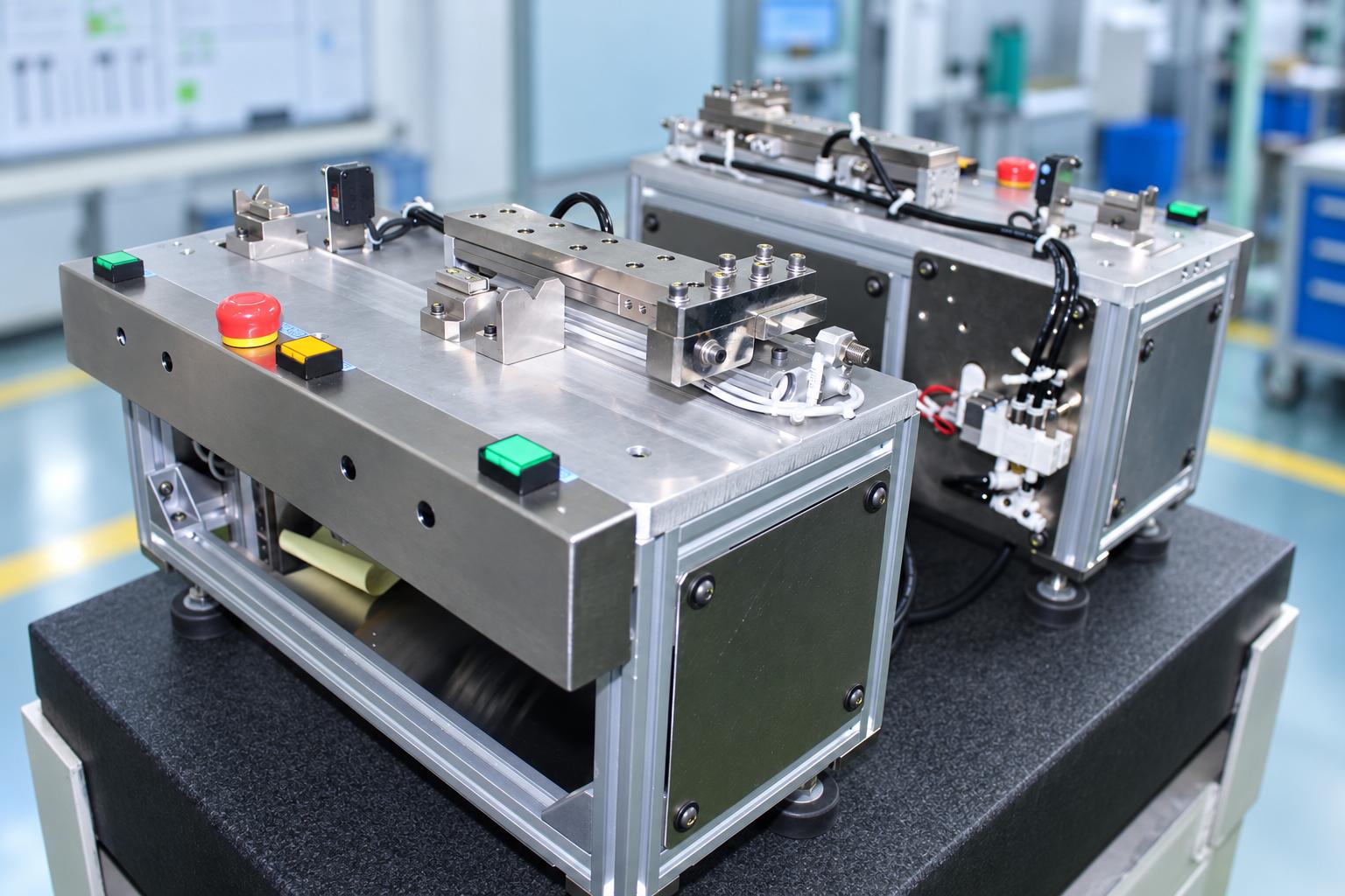
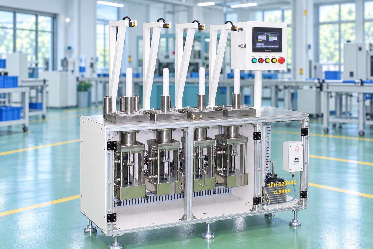
Automatic stainless steel shaft insertion and rubber cutting machine integrates material feeding, positioning, stainless steel core insertion, roller pressing, rubber trimming, and excess material removal into a single system. The machine features separate feeding units, an air-assisted insertion mechanism, and two cutting tool fixtures to process shaft assemblies according to technical drawings.
Upon completion, the finished product consists of an outer rubber body with both ends of the stainless steel shaft exposed to the specified dimensions. The PLC and HMI system coordinates the operating sequence while monitoring production counts, cycle times, and error status. CNC VINA customizes the machine configuration based on material specifications, quality requirements, and the production conditions of each factory.
VIETNAM CNC & TECHNOLOGY APPLICATION JOINT STOCK COMPANY
Hotline: +84.916 63 9355 / +84.915 74 4664
Email: Sales01@cncvina.com.vn / Sales03@cncvina.com.vn
Product description

Automatic stainless steel shaft insertion and rubber cutting machine integrates material feeding, positioning, stainless steel core insertion, roller pressing, rubber trimming, and excess material removal into a single system. The machine features separate feeding units, an air-assisted insertion mechanism, and two cutting tool fixtures to process shaft assemblies according to technical drawings.
Upon completion, the finished product consists of an outer rubber body with both ends of the stainless steel shaft exposed to the specified dimensions. The PLC and HMI system coordinates the operating sequence while monitoring production counts, cycle times, and error status. CNC VINA customizes the machine configuration based on material specifications, quality requirements, and the production conditions of each factory.
What is a stainless steel shaft insertion and rubber cutting machine?
A stainless steel shaft insertion and rubber cutting machine is an automated system that performs material feeding, positioning, stainless steel core insertion into a rubber body, roller pressing, and trimming of excess rubber. The machine combines mechanical components, pneumatic mechanisms, and PLC control to process shaft assemblies according to product drawings.
Role of the machine in rubber roller assembly production
In rubber roller assembly production, inserting a stainless steel core into the rubber body requires accurate positioning and alignment between the two components. After insertion, the rubber must be trimmed to the specified length while controlling the exposed length of the stainless steel shaft at both ends, cut-edge quality, and the condition of the metal surface. When these operations are performed separately, manufacturers must arrange additional material transfers, positioning, and inspection steps between processes. This may affect the continuity of the manufacturing process.

CNC VINA's automatic shaft insertion machine integrates shaft insertion, roller pressing, cutting, and excess rubber removal into a unified, controlled operating sequence. The workpiece transfer mechanism moves products between processing stations, reducing manual handling and supporting consistent process control.
Finished product quality is evaluated based on rubber length, stainless steel core positioning, cut-edge condition, and product surface quality. Actual production capacity must be verified through sample testing and trial runs under specific manufacturing conditions.
Key features of CNC VINA's stainless steel shaft insertion and rubber cutting machine
- Integrated processing: Combines material feeding, stainless steel shaft insertion, roller pressing, rubber cutting, and excess material removal within a single system.
- Two independent feeding units: Supply stainless steel shafts and rubber bodies to the processing positions in the required sequence.
- Air-assisted insertion mechanism: Combines guided movement, pneumatic cylinders, and compressed air to insert the stainless steel core into the rubber body.
- Post-insertion roller pressing unit: Performs rotational and pressing movements before transferring the product to the cutting station.
- Left and right cutting tool fixtures: Trim the rubber at both ends, incorporating support centers and fine adjustment mechanisms for precise tool positioning.
- Automatic excess material removal: A gripping and transfer mechanism separates the trimmed rubber sections before discharging the finished product.
- PLC and HMI control: Supports manual and automatic operating modes, production count monitoring, cycle time tracking, and error history recording.
The features listed above represent CNC VINA's reference machine configuration. Processing compatibility for each product depends on its dimensions, materials, fixtures, and actual trial-run results.
Structure and technology of the automatic shaft insertion machine
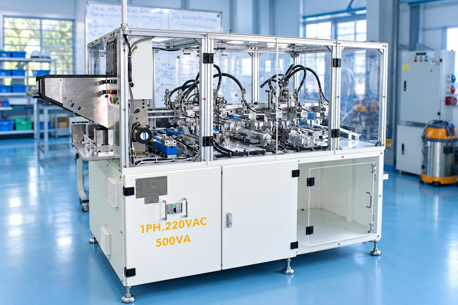
Stainless steel shaft and rubber feeding units
The machine uses two separate feeding units for stainless steel shafts and cylindrical rubber bodies. Stopper, pushing, and workpiece transfer mechanisms deliver individual components to their designated pickup positions according to the control program. Sensors help verify the presence of workpieces before subsequent operations begin. The feeding system design depends on the diameter, length, straightness, and surface condition of the components. For rubber parts, elasticity and dimensional variations between production batches also affect feeding stability. When changing product specifications, workpiece separation, guiding, and transfer performance must be checked before adjusting the operating speed.
Positioning and stainless steel shaft insertion unit
This is the main assembly unit of the stainless steel shaft insertion machine. The positioning mechanism establishes the required alignment between the stainless steel core and the rubber body. The insertion mechanism then uses guided motion and pneumatic cylinders to insert the shaft into the rubber body. The system features an air-assisted insertion circuit incorporating an air filter, pressure regulator, air reservoir, and pressure booster. These components establish the pneumatic conditions required by the insertion mechanism. The air pressure used during insertion must be determined according to the machine design and should not automatically be assumed to be equal to the main air supply pressure. Alignment between the stainless steel shaft, rubber body, and guiding mechanism directly affects assembly quality. When processing a new product, the shaft diameter, end geometry, straightness, and workpiece holding stability during insertion must be checked. The fixtures must provide suitable positioning while minimizing unwanted contact or damage to the stainless steel and rubber surfaces.
Post-insertion roller pressing unit
After the stainless steel core has been inserted into the rubber body, the assembly is transferred to the roller pressing unit. The rollers perform rotational movements in coordination with a pressing or holding mechanism according to the programmed sequence. Contact conditions between the rollers and the product are established based on the diameter, elasticity, and surface characteristics of the rubber. This operation takes place before the cutting station as part of the overall shaft assembly process. During trial runs, the product surface condition after roller pressing, workpiece holding stability, and relative positioning between the rubber body and stainless steel core must be evaluated before the product proceeds to the next operation.
Dual-end rubber cutting unit and fine tool adjustment mechanism
The cutting unit of the stainless steel shaft insertion and rubber cutting machine features two cutting tool fixtures positioned on the left and right sides. At the cutting station, the product is supported at both ends and rotated by a drive mechanism. The cutting tools advance toward the cutting areas to trim the rubber to the specified dimensions. The purpose of this operation is to achieve the required rubber body length and exposed stainless steel shaft lengths according to the product drawing. The machine trims the rubber rather than shortening the stainless steel core.
A center support mechanism holds the shaft during rotation and cutting. If the holding components become worn or positioning becomes unstable, the workpiece may slip, the rubber may not be completely cut, or scratches may appear on the stainless steel surface. Both cutting tool fixtures feature fine adjustment mechanisms for setting the cutting positions. Quick-release knobs facilitate disassembly during tool replacement or maintenance. After adjustment, sample products must be processed to verify rubber length, cut-edge quality, and the condition of the stainless steel surface. For a dual-end rubber cutting machine, processing quality depends on blade sharpness, cutting position, shaft holding stability, and material properties. Therefore, cutting tool inspection should be performed together with checks of the related positioning and drive mechanisms.
Excess rubber removal and finished product collection unit
After cutting, the product is transferred to the excess material removal unit. A gripping and transfer mechanism separates the trimmed rubber sections from the shaft assembly. The workpiece transfer system then delivers the finished product to a collection box. The effectiveness of excess rubber removal depends on cutting quality. If the rubber is not completely severed, the excess material may remain attached to the product and affect subsequent operations. Depending on surface protection requirements, the finished product collection method can be customized using dedicated trays or a separate unloading mechanism during the machine design process.
PLC control system and HMI
The PLC coordinates the feeding, positioning, insertion, roller pressing, cutting, excess material removal, and product transfer units. Sensor signals are used to verify workpiece positions, actuator status, and the conditions required to proceed to the next operation. The HMI supports manual and automatic operation, mechanism homing, production trials with preset quantities, and cycle completion functions. The interface displays machine status, production counts, processing times, and error history. The sensors are used for sequence control and do not replace dimensional inspection or product surface quality evaluation. If automatic post-cutting inspection is required, it must be specified separately within the machine design scope.
Working principle of the stainless steel shaft insertion and rubber cutting machine
The stainless steel shaft insertion and rubber cutting machine operates under PLC control, coordinating material feeding, shaft insertion, roller pressing, cutting, and finished product collection.
The basic operating sequence includes:
- Material preparation: The operator loads stainless steel shafts and rubber bodies into their respective feeding units and checks the power supply, compressed air supply, fixtures, and machine status.
- Feeding and positioning: The feeding mechanisms deliver each type of workpiece to its pickup position. The transfer system moves the stainless steel shaft and rubber body to the insertion unit.
- Stainless steel shaft insertion: The guiding mechanism works together with pneumatic cylinders and the air-assisted system to insert the stainless steel core into the rubber body.
- Roller pressing: The assembly is transferred to the roller pressing unit, where rotational and pressing movements are performed according to the programmed settings.
- Rubber trimming: The holding mechanism positions and rotates the product while the two cutting tool fixtures advance to trim the rubber at both ends.
- Excess material removal: The gripping mechanism separates the trimmed rubber sections from the shaft assembly.
- Finished product collection: The transfer mechanism delivers the completed product to the collection box, while the system continues the operating cycle when all required conditions are met.
During operation, the PLC monitors sensor signals and actuator status. If a stroke error, material shortage, or unmet interlock condition occurs, the machine responds according to its programmed alarm procedures. Before continuous production begins, trial runs and inspections must be conducted to verify rubber length, exposed stainless steel shaft lengths at both ends, cut-edge quality, and product surface condition.
Applications of the stainless steel shaft insertion and rubber cutting machine
Manufacturing rubber-covered stainless steel shaft assemblies
The machine's primary application is inserting a stainless steel core into a cylindrical rubber body, followed by roller pressing and trimming at both ends. The finished product consists of an outer rubber body with both metal ends exposed according to the product drawing. This configuration is suitable for repetitive processing of shaft assemblies whose dimensions and structures are compatible with the feeding system, fixtures, and cutting mechanisms.
Batch production of rubber shaft assemblies
In batch manufacturing, the rubber shaft core insertion machine integrates insertion, roller pressing, and trimming operations into a single system. The operator is responsible for replenishing materials, monitoring machine status, and collecting finished products at the output. This integrated approach supports a consistent processing sequence and facilitates the control of core positioning, rubber length, and cut-edge quality requirements.
Customized roller component manufacturing
For components intended for use as rollers in feeding or conveying mechanisms, CNC VINA can evaluate customized machine designs based on inserting a metal core into an elastomeric body. Application feasibility depends on material properties, diameter, length, core straightness, and surface requirements. Characteristics such as runout, adhesion, and load-bearing capacity require separate evaluation methods based on the specifications of each product.
Technical specifications of the stainless steel shaft insertion and rubber cutting machine
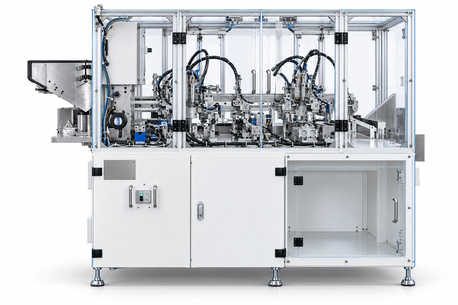
| Parameter | Reference specification |
|---|---|
| Functions | Material feeding, stainless steel shaft insertion, roller pressing, rubber cutting, and excess material removal |
| Input materials | Stainless steel shafts and cylindrical rubber bodies |
| Power supply | AC 220 V, single-phase, 50 Hz |
| Rated electrical power | 0.5 kW |
| Control voltage | DC 24 V |
| Machine air supply pressure | 0.4–0.6 MPa |
| Machine dimensions (W × D × H) | 1050 × 2150 × 1350 mm |
| Operating height | 800 ± 50 mm |
| Insertion mechanism | Guiding mechanism, pneumatic cylinders, and air assistance |
| Cutting mechanism | Two cutting tool fixtures, center support mechanism, and fine adjustment system |
| Control system | PLC and HMI |
| Operating modes | Manual and automatic |
| Monitoring functions | Production count, processing time, and error history |
| Output | Finished products transferred to a collection box after excess rubber removal |
The above specifications represent the nominal configuration stated in CNC VINA's catalogue. The rated electrical power of 0.5 kW does not include the electricity consumed by external compressed air supply equipment. Actual production capacity depends on workpiece specifications, cycle time, feeding conditions, and quality requirements. During installation, sufficient space must be provided for material replenishment, finished product collection, maintenance door access, and operation of the machine mechanisms.
Selection criteria for a stainless steel shaft insertion and rubber cutting machine
Stainless steel shaft and rubber body specifications
Manufacturers should provide technical drawings or samples of the stainless steel shaft, rubber body, and completed assembly. Important information includes diameter, length, straightness, material properties, and final dimensions after processing. These specifications form the basis for designing the feeding mechanisms, fixtures, insertion stroke, and cutting tool positions.
Shaft insertion requirements and post-cutting quality
The required rubber body length after cutting, exposed stainless steel shaft lengths at both ends, and permissible dimensional deviations must be clearly defined. Requirements for cut-edge quality, burrs, residual rubber, and stainless steel core surface condition should also be agreed upon. For products with strict appearance requirements, approved reference samples and limit samples should be used as the basis for inspection and acceptance.
Flexibility for different product specifications
When changing workpiece diameters or lengths, adjustments may be required to the guiding components, fixtures, shaft holding mechanisms, and cutting tool positions. The range of products that can share the same mechanisms must be confirmed for each product group. Changing operating parameters alone does not replace necessary mechanical adjustments. After each product changeover, the first processed sample must be inspected before batch production begins.
Production capacity and automation level
When selecting a machine, manufacturers should define their target production output, material replenishment method, finished product collection frequency, and output inspection requirements. If dimensional measurement, visual inspection, or automatic sorting is required, these functions must be included in the machine design scope. The existing control sensors should not be assumed to satisfy product quality inspection requirements.
Frequently asked questions about the stainless steel shaft insertion and rubber cutting machine
Does the machine cut the stainless steel core to a shorter length?
No. The presented configuration inserts the stainless steel core into the rubber body and then trims the rubber at both ends. If the metal core also needs to be shortened, an additional cutting method and suitable cutting mechanism must be specified.
Can the machine automatically inspect dimensions after cutting?
The sensors in the reference configuration are used to detect workpiece presence and actuator positions. The HMI supports production count monitoring, processing time tracking, and alarm display. Automatic length measurement, surface inspection, or sorting based on measurement results requires additional system design if requested.
Can the machine process different types of rubber shaft assemblies?
The machine can be designed to accommodate multiple product specifications, provided they are compatible with the feeding, insertion, roller pressing, and cutting mechanisms. Changes in diameter, length, or material may require adjustments to fixtures, holding mechanisms, and cutting tool positions. Changeover capability must be verified through sample testing.
Does the machine automatically remove excess rubber?
Yes. After cutting, a gripping and transfer mechanism separates the excess rubber sections from the shaft assembly. Stable removal performance depends on cutting quality, material characteristics, and the operating condition of the separation mechanism.
CNC VINA – Customized stainless steel shaft insertion and rubber cutting machine design and manufacturing
CNC VINA's stainless steel shaft insertion and rubber cutting machine integrates material feeding, positioning, stainless steel core insertion, roller pressing, rubber trimming, and excess material removal into a single automated system. The equipment is designed according to stainless steel shaft specifications, rubber body characteristics, final product dimensions, and the quality requirements of each application.
With experience in industrial machine design, manufacturing, and automation systems, CNC VINA provides customized solutions suited to manufacturers' production conditions. Depending on project requirements, the machine configuration can be adapted in terms of feeding mechanisms, fixtures, insertion technology, cutting positions, and finished product collection methods. Before project implementation, manufacturers are encouraged to provide technical drawings or actual product samples so that CNC VINA can evaluate processing feasibility, propose an appropriate machine configuration, and establish mutually agreed acceptance criteria.
Contact CNC VINA for consultation on customized automatic stainless steel shaft insertion and rubber cutting machines.
VIET NAM TECHNOLOGY APPLICATION AND CNC JOINT STOCK COMPANY
Factory: Song Cung Industrial Cluster, Dong Thap Commune, Dan Phuong District, Hanoi, Vietnam.
Office: Rox Tower Goldmark City, 136 Ho Tung Mau Street, Phu Dien Ward, Hanoi, Vietnam.
Hotline/Zalo: +84 916 639 355 / +84 915 744 664
Websites: www.cncvina.com.vn | www.cncvina.net