 Tiếng
Việt
 Tiếng
Anh
 Tiếng
Nhật




 Tiếng Anh

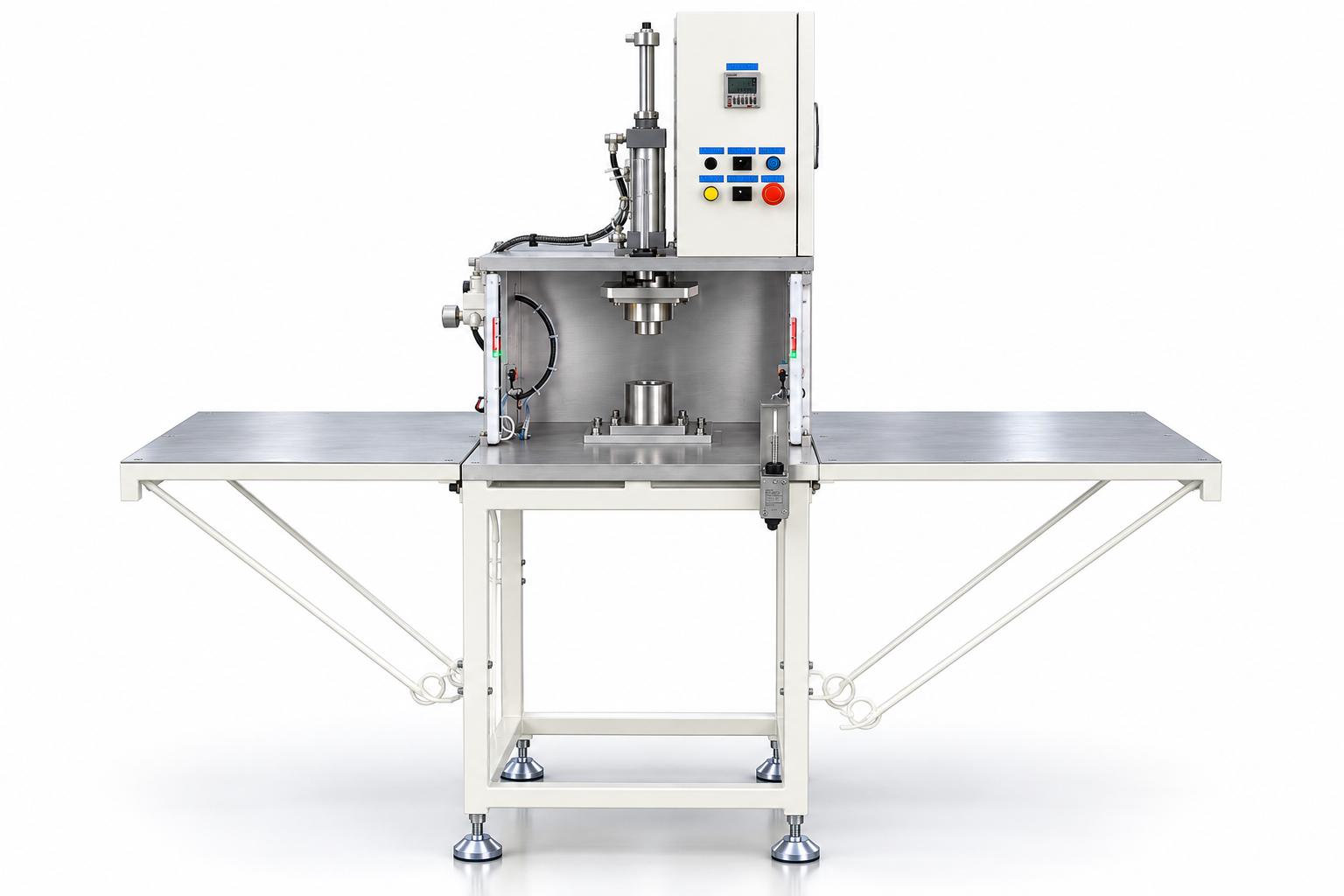
Pneumatic component assembly press
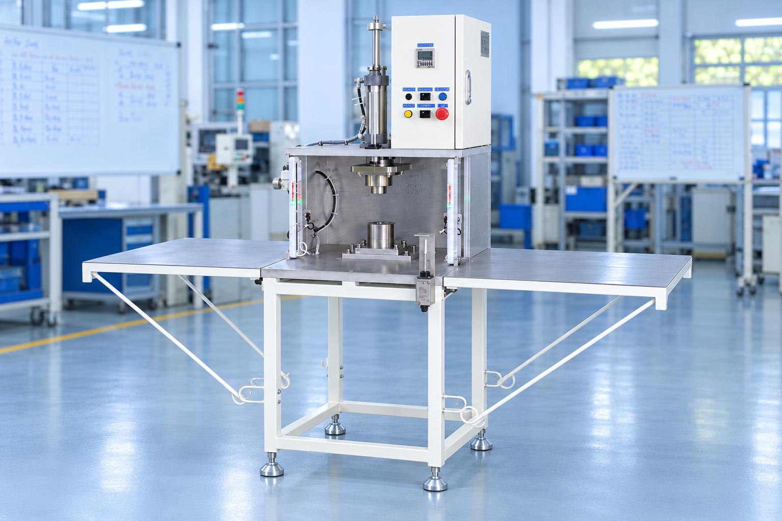
Pneumatic component assembly press is designed for assembly operations requiring a vertically applied pressing force. The machine integrates a pneumatic cylinder, positioning fixtures, and a PLC control system to perform the pressing sequence according to the configured settings. The operator places the components into the fixture, initiates the pressing cycle, and removes the assembled product once the press head returns to its initial position. The machine supports both manual and automatic operating modes, enabling controlled and consistent operation throughout the production process. The positioning fixtures and stroke-limiting mechanism are designed according to the component geometry, assembly requirements, and actual operating conditions.
VIETNAM CNC & TECHNOLOGY APPLICATION JOINT STOCK COMPANY
Hotline: +84.916 63 9355 / +84.915 74 4664
Email: Sales01@cncvina.com.vn / Sales03@cncvina.com.vn
Product description

Pneumatic component assembly press is designed for assembly operations requiring a vertically applied pressing force. The machine integrates a pneumatic cylinder, positioning fixtures, and a PLC control system to perform the pressing sequence according to the configured settings. The operator places the components into the fixture, initiates the pressing cycle, and removes the assembled product once the press head returns to its initial position. The machine supports both manual and automatic operating modes, enabling controlled and consistent operation throughout the production process. The positioning fixtures and stroke-limiting mechanism are designed according to the component geometry, assembly requirements, and actual operating conditions.
What is a pneumatic component assembly press?
A pneumatic component assembly press is a machine that uses a pneumatic cylinder to generate the pressing motion required to assemble components into their specified positions. Positioning fixtures secure and align the workpieces, while the control system coordinates the pressing and return sequences.
Structure of the pneumatic component assembly press
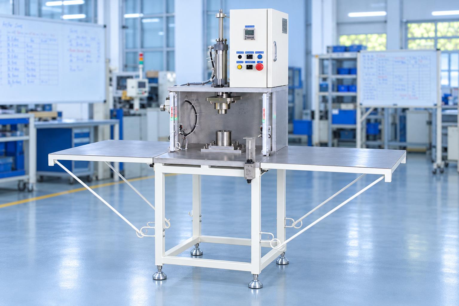
1. Pneumatic pressing mechanism
The pressing mechanism uses a pneumatic cylinder to move the press head vertically. The air supply pressure and working stroke must be suitable for the assembly requirements of each product. When designing the machine, the required pressing force should be determined based on component characteristics, interference fit tolerances, or joint requirements, rather than selecting the mechanism solely based on the machine's overall dimensions.
2. Upper and lower positioning fixtures
The upper and lower fixtures hold the components in their designated positions during the pressing process. The locating surfaces and clamping mechanisms must match the product geometry to minimize positional deviations as the press head moves. During initial setup, a centering jig may be used to align the upper and lower fixtures. Once alignment is complete, the centering jig is removed before production begins. It is not intended to serve as an inspection tool for individual finished products.
3. Guide mechanism and stroke limiters
Guide rods and guide bushings help ensure stable movement of the press head along its designated axis. Depending on the machine configuration, a coupling with suitable misalignment compensation may help reduce the effects of minor deviations between the actuator and the press head. Fine adjustment screws and mechanical stroke stops are used to set the required travel limits. Adjustments should be performed during installation, fixture replacement, or product changeovers. It is also necessary to verify that the press head does not collide with the components or fixtures.
4. PLC control system and sensors
The PLC controls the machine's operating sequence according to the programmed settings. Depending on the equipment configuration, the control panel includes buttons such as START, RESET, UP/DOWN, and an emergency stop button. Sensors detect component presence or mechanism positions, providing the signals required to authorize transitions between steps in the operating cycle. The machine may also be equipped with a completed-product counter and an audible alarm that activates when the preset quantity is reached.
Operating principle of the machine
The following sequence describes a typical operating cycle. The actual interlock sequence and conditions for advancing between steps must be verified against the machine's PLC program.
-
Component loading: The operator places the components to be assembled into the lower fixture in the specified orientation and position.
-
Operating condition verification: The system checks the configured input conditions, such as component presence and mechanism positions.
-
Cycle initiation: The operator presses START or selects the appropriate operating mode on the control panel.
-
Pressing operation: The pneumatic cylinder moves the press head downward, pressing the components into their designated assembly positions according to the preset stroke.
-
Pressing cycle completion: The press head maintains its position or changes state according to the programmed sequence before returning to its initial position.
-
Product unloading: The operator removes the assembled product from the fixture. The counter updates when the cycle meets the programmed counting conditions, and the audible alarm activates upon reaching the preset quantity if this function is enabled.
In manual mode, the operator controls individual movements for adjustment or inspection within the permitted control logic. In automatic mode, the machine executes the programmed PLC sequence but may still require manual component loading and unloading. Therefore, AUTO mode does not necessarily mean fully automated feeding or unattended operation.
Applications of the pneumatic component assembly press
The pneumatic component assembly press is suitable for assembly operations that require components to be pressed into position through a controlled pressing motion. Its applicability depends on the product structure, required pressing force, and fixture design.
Typical applications include:
-
Mechanical component press-fitting: Installing bushings, sleeves, or cylindrical components into designated positions when the product design is suitable.
-
Component assembly: Positioning and assembling components before subsequent inspection or finishing operations.
-
Electrical and electronic component assembly: Press-fitting components that require vertically applied force and suitable positioning fixtures.
-
Standardization of assembly operations: Establishing a consistent operating sequence and reducing dependence on manual pressing operations.
Before selecting the machine, manufacturers should determine the required pressing force, working stroke, assembly tolerances, and post-pressing inspection requirements. Not all products are suitable for pneumatic pressing. Applications requiring high pressing forces or precise force–displacement control should be evaluated separately.
Technical specifications of the pneumatic component assembly press
The table below summarizes the reference specifications based on the provided machine configuration. Any specifications not included in the catalogue must be confirmed before finalizing the design.
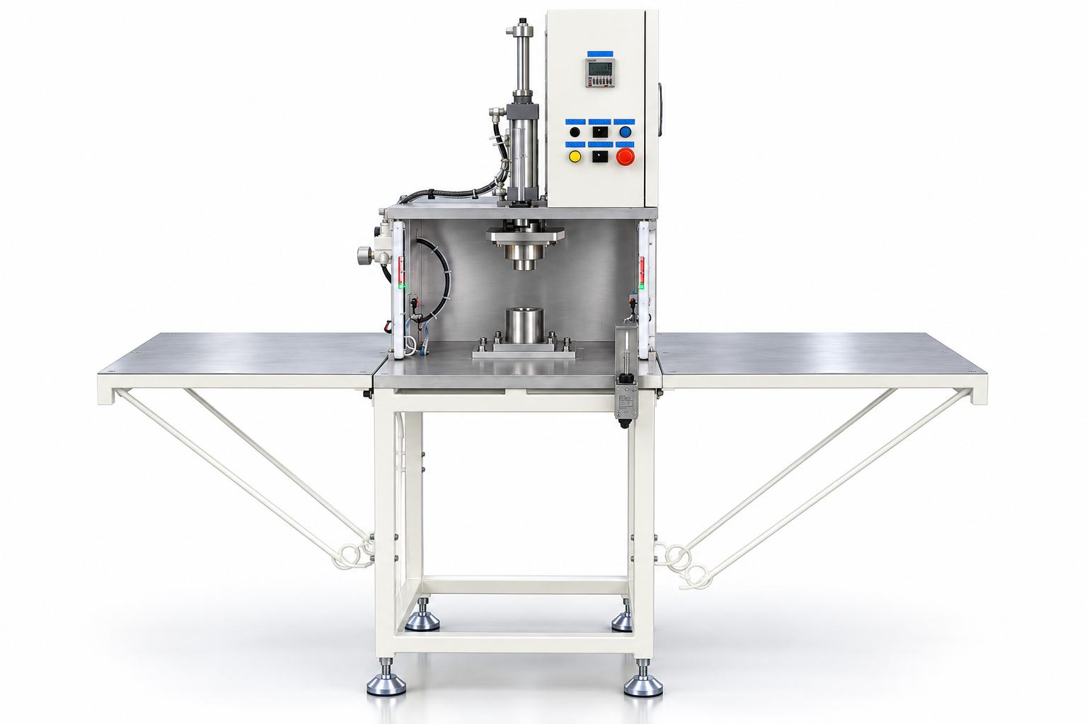
Technical specifications of the pneumatic component assembly press
The following table presents the reference specifications of the machine configuration.
|
Item |
Reference specifications |
|---|---|
|
Drive method |
Pneumatic |
|
Control system |
PLC |
|
Power supply |
AC 220 V, single-phase, 50 Hz |
|
Electrical power consumption |
100 W |
|
Control voltage |
DC 24 V |
|
Compressed air pressure |
0.4–0.6 MPa |
|
Machine dimensions |
1,320 (W) × 485 (D) × 1,600 (H) mm |
|
Working height |
950 ± 50 mm |
|
Operating modes |
Manual and automatic, depending on configuration |
|
Additional functions |
Sensors, product counter, and audible alarm, depending on configuration |
Notes on technical specifications: The overall machine width should be confirmed under the specified measurement conditions, particularly if the machine is equipped with auxiliary tables on both sides. The 100 W rating refers to the machine's electrical power specification stated in the catalogue and does not indicate its pressing force. The pressing force, cylinder bore diameter, working stroke, and cycle time have not yet been verified and are therefore excluded from the table.
How to select a pneumatic component assembly press
To select a machine suitable for the production line, manufacturers should evaluate the following factors.
Determine the required pressing force and stroke
The required pressing force, working stroke, and travel limits of the press head must be determined before selecting the machine. These parameters should be based on material properties, assembly dimensions, and product quality requirements. If the required pressing force has not been established, sample testing is recommended before finalizing the machine configuration.
Design fixtures according to product requirements
The fixtures must securely hold the components, ensure accurate assembly positioning, and allow convenient product removal after the pressing cycle. For production lines handling multiple product models, the fixture replacement method, adjustment capability, and changeover time should be evaluated.
Verify control logic and interlocks
The operating conditions, downward pressing sequence, return movement, counter update criteria, and fault-handling procedures should be clearly defined. Operator protection functions must be determined through a risk assessment and appropriate safety design. The presence of sensors alone does not guarantee machine safety.
Evaluate production line integration
In addition to machine dimensions, manufacturers should consider the working height, component loading and unloading positions, electrical supply, compressed air requirements, and installation space. If the machine is connected to conveyors or other equipment, communication signals and interlocking conditions between the systems must be agreed upon in advance.
Machine inspection and acceptance testing before production
Before delivery, an inspection and acceptance testing plan should be established based on the technical requirements agreed upon by both parties.
-
Mechanical inspection: Verify machine dimensions, structural rigidity, fixture stability, and smooth operation of the guide mechanism.
-
Operating cycle verification: Test each operating step, confirm press head positions, and verify the programmed return sequence.
-
Sensor and interlock verification: Check individual input signals, operating permissions, and system responses when required conditions are not met.
-
Product counter verification: Compare the actual number of completed products with the counter reading and test the audible alarm at the preset quantity.
-
Product sample testing: Evaluate assembly positions, deformation, damage, and other quality criteria specified by the customer.
If the product requires pressing force monitoring, insertion depth verification, or post-assembly dimensional inspection, appropriate measurement methods and acceptance criteria must be established.
The product counter only records quantities according to the programmed control logic and does not replace finished-product quality inspection.
Maintenance of the pneumatic component assembly press
Regular maintenance helps maintain the stability of the pressing mechanism and minimize operational issues during production.
-
Pneumatic system: Check the supply pressure, air hoses, fittings, and potential air leaks.
-
Guide mechanism: Inspect looseness, cleanliness, and lubrication conditions according to the equipment maintenance instructions.
-
Fixtures and stroke stops: Check the tightness of bolts, locating pins, and adjustment positions.
-
Sensors and control panel: Inspect sensor signals, wiring, control buttons, and counter operation.
-
Safety functions: Test the emergency stop and other protective functions according to established inspection and maintenance procedures.
Before cleaning, adjusting fixtures, or performing maintenance within the machine's moving area, all relevant energy sources must be isolated, and any residual pneumatic energy must be safely released according to the factory's safety procedures.
Frequently asked questions about the pneumatic component assembly press
Is the pneumatic component assembly press fully automatic?
Not necessarily. The machine can automatically perform the pressing cycle after the operator loads the components and initiates the operation. Component feeding, product unloading, and transfer to subsequent processes may still require manual intervention.
Can one machine be used to press-fit different products?
Yes, provided that the machine structure and fixture design meet the requirements of each product. Fixture replacement, stroke adjustment, and pressing force requirements must be evaluated before confirming compatibility with multiple product types.
Can the centering jig be used to inspect every product after pressing?
No. In the described configuration, the centering jig is used to align the upper and lower fixtures during machine setup and is removed before production begins. Finished-product inspection requires appropriate measurement methods and instruments based on the specified quality criteria.
What information is required to design a customized pneumatic component assembly press?
Manufacturers should provide product drawings or samples, component materials, assembly requirements, estimated pressing force, working stroke, target production capacity, and post-assembly inspection criteria.
If some specifications are not yet available, the process can begin with sample evaluation and pressing trials to determine a suitable technical solution.
CNC VINA – Customized pneumatic component assembly press design and manufacturing
The pneumatic component assembly press is designed for vertical pressing operations using fixtures tailored to specific products. Its configuration can be developed based on component geometry, positioning references, required pressing force, working stroke, and the factory's operating requirements. CNC VINA can provide customized solutions involving fixture design, guide mechanisms, stroke limiters, and control sequences according to the agreed technical specifications. Before manufacturing, customers are encouraged to provide product drawings or samples along with post-assembly quality criteria to assess technical feasibility. The final machine configuration should be validated through appropriate technical data and testing with actual products.
Contact CNC VINA to discuss your requirements and receive a suitable pneumatic component assembly press solution.
VIETNAM CNC & TECHNOLOGY APPLICATION JOINT STOCK COMPANY (CNC VINA)
Factory: Song Cung Industrial Cluster, Dong Thap Commune, Dan Phuong District, Hanoi, Vietnam.
Office: Rox Tower Goldmark City, 136 Ho Tung Mau Street, Phu Dien Ward, Hanoi, Vietnam.
Phone: +84 916 639 355 / +84 915 744 664
Website: www.cncvina.com.vn | www.cncvina.net
Email: sale01@cncvina.com.vn | sales03@cncvina.com.vn