 Tiếng
Việt
 Tiếng
Anh
 Tiếng
Nhật




 Tiếng Anh

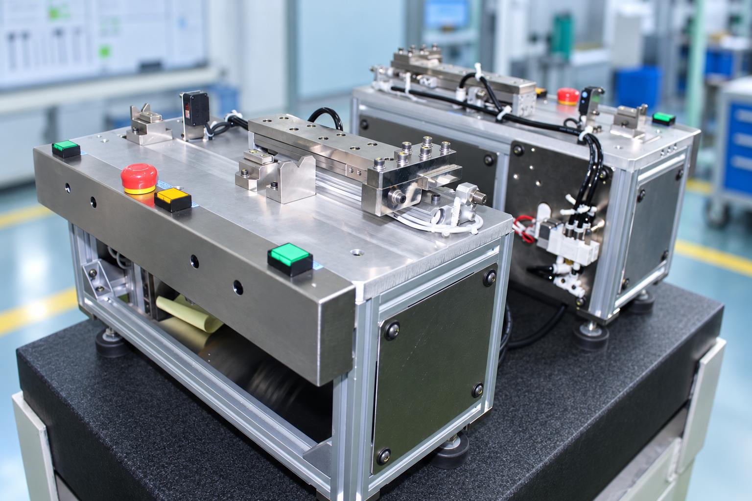
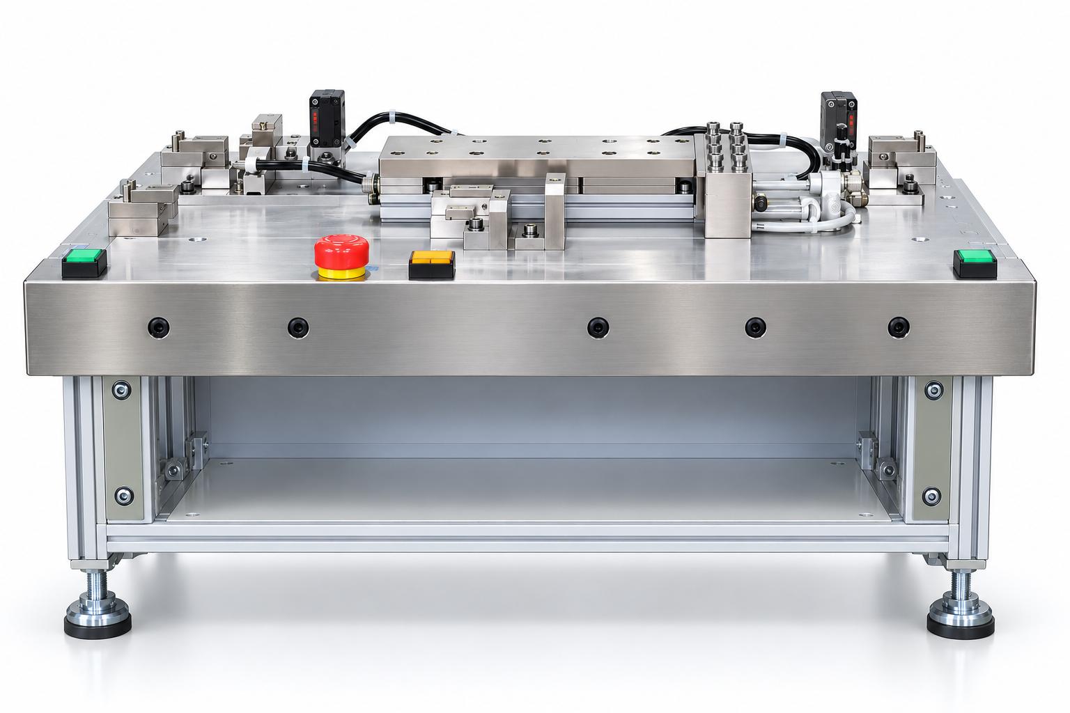
Gear press-fitting machine
Gear press-fitting machine from CNC VINA is a semi-automatic device that uses a pneumatic cylinder to press-fit gears onto roller assemblies horizontally. The machine features positioning fixtures, a pressing mechanism, a stopper mechanism, and a sensor system to coordinate movements throughout the assembly process. The operator manually loads the components, presses two start buttons simultaneously, and removes the assembled product after the cycle is completed.
VIETNAM CNC & TECHNOLOGY APPLICATION JOINT STOCK COMPANY
Hotline: +84.916 63 9355 / +84.915 74 4664
Email: Sales01@cncvina.com.vn / Sales03@cncvina.com.vn
Product description

Gear press-fitting machine from CNC VINA is a semi-automatic device that uses a pneumatic cylinder to press-fit gears onto roller assemblies horizontally. The machine features positioning fixtures, a pressing mechanism, a stopper mechanism, and a sensor system to coordinate movements throughout the assembly process. The operator manually loads the components, presses two start buttons simultaneously, and removes the assembled product after the cycle is completed.
The machine mechanizes the press-fitting process, reducing the need for manual force while helping maintain proper assembly alignment through dedicated fixtures. Its tabletop design makes it suitable for semi-automatic assembly stations in factories manufacturing mechanical components and assemblies. CNC VINA can customize the fixtures, pressing mechanism, and control system according to the dimensions and specific requirements of each product.
What is a gear press-fitting machine?
A gear press-fitting machine is a device that uses a pressing mechanism to install gears onto shafts or component assemblies at specified positions. CNC VINA's gear press-fitting machine combines a pneumatic cylinder, positioning fixtures, and sensors to perform semi-automatic assembly operations. During roller assembly, the gear must be installed at the specified position on the shaft according to the product's design requirements. The direction of the pressing force, shaft support positions, and fixture accuracy directly affect the assembly process.
CNC VINA's gear-to-shaft assembly machine uses a horizontal pressing mechanism to perform the assembly operation. The roller assembly is placed on supporting fixtures, while the gear is positioned in alignment with the shaft end. Once the start command is received and all operating conditions are met, the pneumatic cylinder pushes the gear into its designated position. This solution is suitable for manufacturing processes that require mechanized press-fitting while retaining manual component loading and unloading.
Features and benefits of the gear press-fitting machine
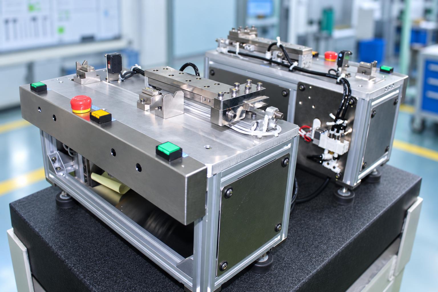
CNC VINA's semi-automatic gear press-fitting machine is designed based on the characteristics of the roller assembly and actual production requirements. The machine integrates pneumatic mechanisms, dedicated fixtures, and a control system to execute the assembly cycle in a predefined sequence.
Key features
- Pneumatic press-fitting: A pneumatic cylinder drives the gear horizontally into the roller assembly, eliminating the need to apply pressing force manually.
- Dedicated positioning fixtures: The shaft supports and gear positioning points are designed to accommodate the shape and dimensions of the assembly.
- Coordinated stopper mechanism: Provides a support position during press-fitting and lowers to allow removal of the assembled product.
- PLC and sensor control: Coordinates product presence signals, actuator position feedback, and mechanical movements throughout the operating cycle.
- Semi-automatic operation: The operator loads the components, presses two Start buttons simultaneously, and removes the assembled product. The machine is equipped with a Reset button, an emergency stop, and visual and audible status indicators.
Benefits in manufacturing
Reduced manual press-fitting operations
Instead of relying on manual force or hand-operated pressing tools, the pneumatic press-fitting machine uses a cylinder-driven mechanism to perform the pressing operation. Operators focus on component preparation, positioning, and unloading, establishing a clear division between manual handling and machine-controlled movements.
Improved assembly alignment
The gear press-fitting fixtures are designed specifically for the assembly, providing shaft support and guiding gear positioning before pressing. Proper fixture alignment helps minimize positioning errors caused by incorrect component placement. The quality of the press-fit joint must still be verified against the specified tolerances and product acceptance criteria.
Controlled operating sequence
The PLC and sensor system monitors start conditions, the forward and return movements of the pressing mechanism, and the position of the stopper mechanism. If the required operating conditions are not met, the machine can generate alerts for operator inspection.
Suitable for semi-automatic assembly stations
The tabletop machine can be integrated into gear assembly stations where components are manually loaded and unloaded. For higher levels of automation, additional component feeding, unloading, or post-assembly inspection mechanisms can be considered based on production requirements.
Structure of the pneumatic gear press-fitting machine
CNC VINA's gear press-fitting machine consists of several main components: positioning fixtures, a pneumatic pressing assembly, a stopper mechanism, sensors, a PLC controller, and a pneumatic system. These components are arranged according to the gear installation direction on the roller assembly while providing sufficient working space for operators to load and unload products.
Positioning fixtures and shaft supports
The positioning fixtures hold the roller assembly in the correct orientation during press-fitting. Shaft supports are arranged along the roller shaft to maintain the product in a horizontal position. The support surfaces are shaped to match the roller shaft profile, with magnets assisting in holding the components in the current machine configuration. The gear is positioned at the designated installation point, aligned with the shaft end and the movement direction of the pressing mechanism. When designing gear press-fitting fixtures, key considerations include reference surfaces, spacing between shaft supports, contact areas, and load-bearing positions. For long shafts or components with sensitive surfaces, the fixture design must provide adequate support throughout the pressing operation.
For applications involving different roller sizes, CNC VINA can evaluate the use of interchangeable or adjustable fixtures for specific product groups.
Pneumatic pressing assembly and stopper mechanism
The pressing assembly uses a pneumatic cylinder to install the gear onto the roller shaft. The pressing head contacts a designated area of the gear and moves horizontally to perform the press-fitting operation. A guiding mechanism helps maintain the intended direction of the pressing head. Pneumatic valves and flow control valves regulate the extension and retraction of the cylinder. The required pressing force and working stroke must be selected according to the shaft and gear dimensions, type of fit, and technical requirements of the product. These parameters are determined during machine design and sample testing. In addition to the pressing assembly, the machine features a stopper mechanism that provides a supporting position during press-fitting. Once the pressing head has retracted, the stopper lowers to allow the operator to remove the completed assembly. After the product is removed and the required position conditions are satisfied, the stopper returns to its raised position in preparation for the next cycle.
Sensors and PLC control system
CNC VINA's semi-automatic assembly machine uses a photoelectric sensor to detect the presence of the roller assembly on the fixture. Position sensors monitor the extended and retracted positions of the pressing cylinder, as well as the raised and lowered positions of the stopper mechanism.
Sensor signals are transmitted to the PLC, which coordinates the mechanisms according to the programmed operating sequence.
The main control functions include:
- Receiving start commands from two Start buttons.
- Checking product presence signals and actuator positions.
- Controlling pneumatic valves to execute the press-fitting cycle.
- Monitoring position feedback to coordinate mechanical movements.
- Supporting Reset operations and generating alerts when conditions require inspection.
The sensors in the current configuration are used for status detection and cycle coordination; they do not replace a dedicated press-fit quality inspection system. If pressing force monitoring, gear position measurement, or automatic quality evaluation is required, CNC VINA can assess the integration of additional measurement sensors and inspection solutions.
Pneumatic system and operator controls
The pneumatic system consists of an air filter, pressure regulator, control valves, air lines, and pneumatic cylinders. Compressed air is supplied to the pressing and stopper mechanisms to execute movements according to the control program. The operator control panel is positioned for convenient access and includes two Start buttons, a Reset button, an emergency stop, and visual and audible status indicators. During installation, the power supply, air pressure, pneumatic connections, stability of the worktable, and available space for product loading and unloading must be checked.
Working principle of the gear press-fitting machine
The gear press-fitting machine operates in a semi-automatic cycle. The operator manually loads the components and removes the assembled product, while the PLC controls the pneumatic mechanisms based on sensor feedback.
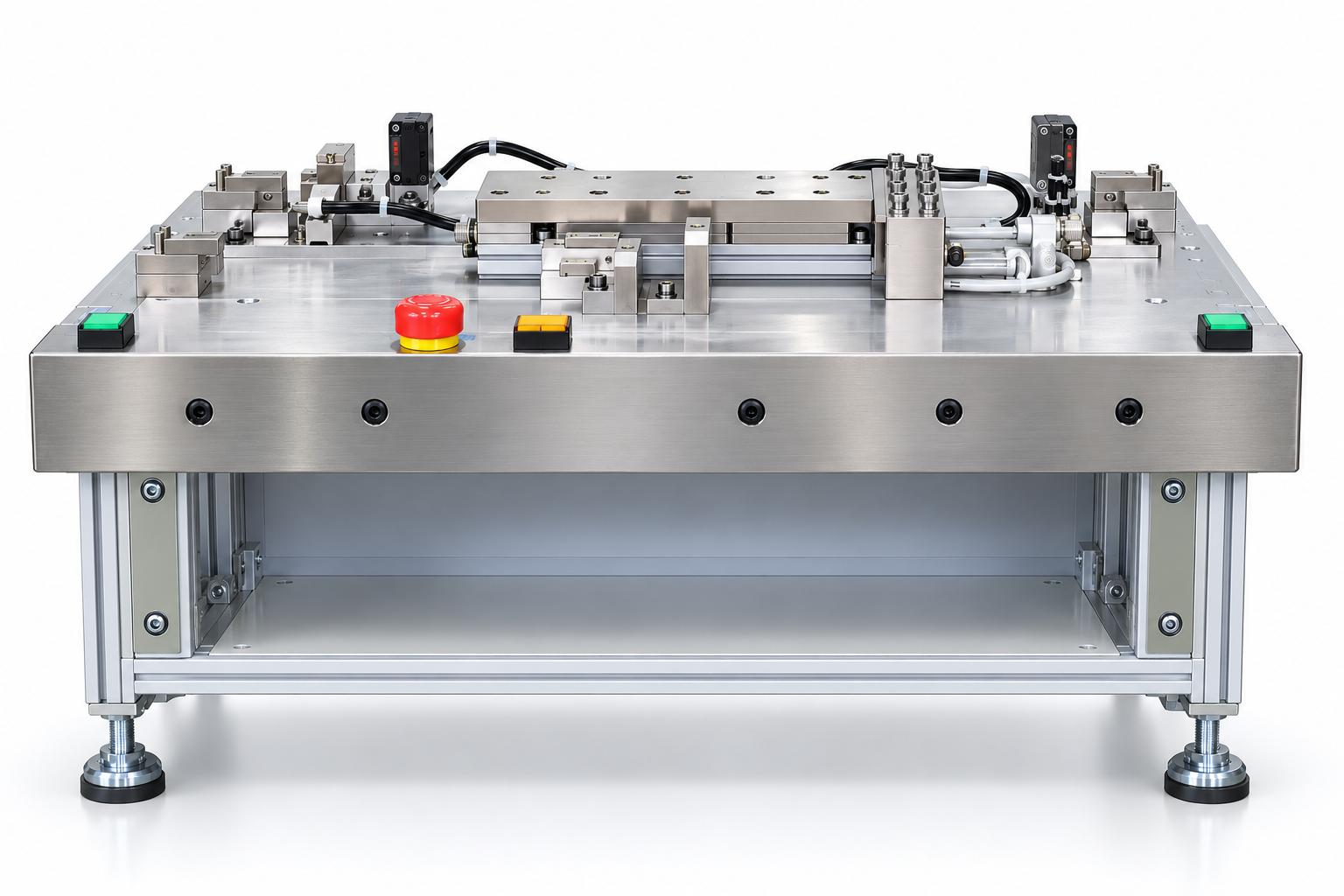
Step 1: Preparation and machine initialization
The operator checks the positioning fixtures, pressing head, power supply, compressed air supply, and operating conditions. In the home position, the pressing cylinder is retracted, and the stopper mechanism is raised. The Reset button is used to initialize or restore the machine to its designated state according to the operating instructions.
Step 2: Loading the roller assembly and gear
The roller assembly is placed on the shaft supports of the positioning fixture. The gear is positioned at the designated installation point corresponding to the shaft end. A photoelectric sensor detects the presence of the roller assembly. Before starting the machine, the operator checks the positioning of the assembly and gear.
Step 3: Gear press-fitting operation
Once all required operating conditions are satisfied, the operator presses the two Start buttons simultaneously. The PLC controls the pneumatic cylinder to extend horizontally, pressing the gear onto the roller shaft. When the mechanism reaches the programmed stroke position, the pressing head retracts to its initial position.
Step 4: Unloading the assembled product
After the pressing head has retracted, the stopper mechanism lowers to provide sufficient clearance for product removal. The operator removes the completed roller and gear assembly from the fixture. Once the product presence signals and mechanism positions meet the required conditions, the stopper rises to its preparation position for the next cycle. During operation, if a product presence signal is missing or a mechanism has not reached its required position, the machine must be inspected before restarting. If components have been loaded but the press-fitting operation has not been performed, the operator must follow the machine's handling instructions and warning procedures.
Technical specifications of the gear press-fitting machine
The following table presents the reference technical specifications of CNC VINA's gear press-fitting machine for roller assemblies. The actual configuration can be customized according to product requirements and production conditions.
| Parameter | Reference specification |
|---|---|
| Application | Press-fitting gears onto roller assemblies |
| Assembly method | Horizontal press-fitting |
| Operating mode | Semi-automatic |
| Actuators | Pneumatic pressing cylinder and stopper cylinder |
| Power supply | AC 220 V, single-phase |
| Control voltage | DC 24 V |
| Rated power capacity (catalogue) | 0.1 kVA |
| Reference air pressure | 0.5 MPa |
| Reference machine cycle time | 4 seconds |
| Control system | PLC |
| Sensors | Product presence and position sensors |
| Operator interface | Two Start buttons, Reset button, emergency stop, indicator lights, and buzzer |
| Installation | Tabletop installation |
Note: The 4-second cycle time is a reference value. Its measurement scope must be confirmed during trial operation and is not sufficient on its own to determine actual production output. Component loading, product unloading, and handling of operational interruptions must be considered separately if they are not included in the stated cycle time.
The operating air pressure and rated power capacity must be verified against the actual machine configuration. The 0.1 kVA value does not represent the total energy consumption of the complete system, including compressed air generation equipment.
Applications of gear press-fitting machines in manufacturing
CNC VINA's gear press-fitting machine is developed specifically for installing gears onto roller assemblies. Its positioning and pneumatic press-fitting principles can also be evaluated for the design of other mechanical assembly stations.
Gear installation on roller assemblies
This is the primary application of the machine. The equipment presses a gear onto a designated position on the roller shaft before the assembly proceeds to inspection or subsequent assembly operations. The machine is suitable for products with a defined assembly direction, components that can be positioned using dedicated fixtures, and press-fit requirements within the capability of the pneumatic pressing mechanism.
Assembly of small power transmission units
For small power transmission assemblies that require gears to be installed on shaft ends, manufacturers can consider a solution combining shaft support fixtures and horizontal press-fitting. When adapting the solution to different products, component dimensions, materials, fit types, pressing force, and contact positions must be determined. The fixtures and actuators must be designed to meet the requirements of each specific assembly.
Customized pulley and bushing assembly stations
In addition to gears, the press-fitting principle can be evaluated for components such as pulleys, bushings, and other parts requiring installation onto shafts. These are potential customized applications rather than standard functions of the current machine. CNC VINA evaluates feasibility based on technical drawings, product samples, and process requirements before proposing an appropriate machine configuration.
Integration into semi-automatic assembly lines
The roller assembly machine features a tabletop design, making it suitable for installation as an individual station within a production line. During integration, manufacturers should consider component loading trays, finished-product collection trays, operator working space, and the cycle times of upstream and downstream processes. If automatic component feeding or product unloading is required, CNC VINA can evaluate the integration of additional mechanisms as part of a customized machine design.
Frequently asked questions about the gear press-fitting machine
Does CNC VINA's gear press-fitting machine support automatic feeding?
The current machine configuration operates semi-automatically. The operator manually loads the gear and roller assembly into the fixture and removes the completed product. The machine automatically performs the programmed press-fitting movement. CNC VINA can evaluate the addition of an automatic feeding system upon request.
Can the machine inspect the quality of the press-fit joint?
The existing sensors detect the presence of the roller assembly and monitor actuator positions. Automatic press-fit quality inspection requires additional force measurement, position monitoring, or other inspection methods based on the product's acceptance criteria.
Can the machine accommodate different gear and roller sizes?
The machine can be designed for a group of products with different dimensions. Compatibility depends on component sizes, installation positions, pressing force, and fixture adjustment range. The specific configuration must be validated through sample testing.
Does the 4-second cycle time represent the total time required to complete one product?
The 4-second cycle time is a reference specification, and its measurement scope must be confirmed during trial operation. Actual production time must also account for component loading, product unloading, and the operating conditions of the assembly station.
What information should manufacturers provide when requesting a customized machine?
Manufacturers should prepare technical drawings, gear and roller assembly samples, post-assembly quality requirements, target production output, and installation conditions. This information enables CNC VINA to select suitable fixtures, pressing mechanisms, and control solutions.
CNC VINA – Customized gear press-fitting machine design and manufacturing
With extensive experience in industrial machine design, manufacturing, and automation systems, CNC VINA provides customized gear press-fitting solutions tailored to manufacturers' product characteristics and production requirements. Each machine is developed based on technical drawings, actual product samples, and the specific technical criteria of the assembly process.
In addition to the semi-automatic gear press-fitting machine for roller assemblies, CNC VINA can evaluate modifications to positioning fixtures, pressing mechanisms, and control systems, as well as the integration of additional functions upon request. The design process involves defining the required pressing force, working stroke, installation position, and quality inspection methods. Machine performance and suitability are evaluated through product trials and mutually agreed acceptance criteria.
Explore CNC VINA's semi-automatic assembly machines and customized press-fitting solutions to identify equipment suited to your manufacturing processes.
VIET NAM TECHNOLOGY APPLICATION AND CNC JOINT STOCK COMPANY
Factory: Song Cung Industrial Cluster, Dong Thap Commune, Dan Phuong District, Hanoi, Vietnam.
Office: Rox Tower Goldmark City, 136 Ho Tung Mau Street, Phu Dien Ward, Hanoi, Vietnam.
Phone: +84 916 639 355 / +84 915 744 664
Websites: https://cncvina.com.vn ; https://cncvina.net ; https://cncviname.com.vn