 Tiếng
Việt
 Tiếng
Anh
 Tiếng
Nhật




 Tiếng Anh

Automatic cable punching machine
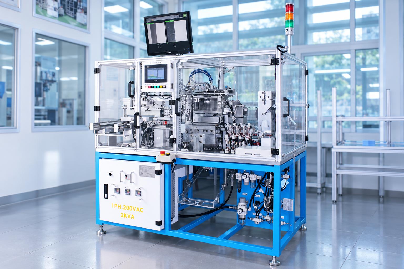
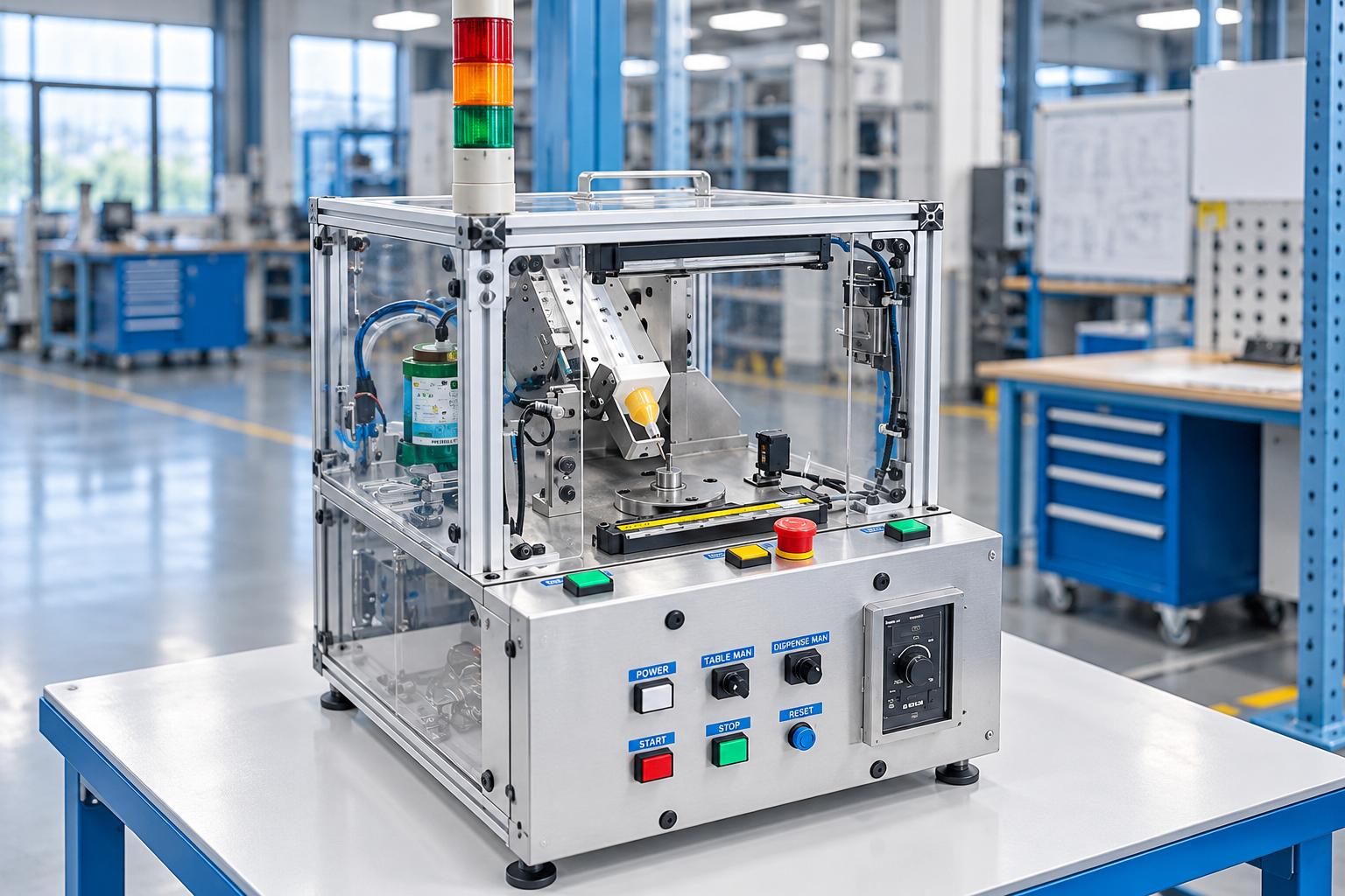
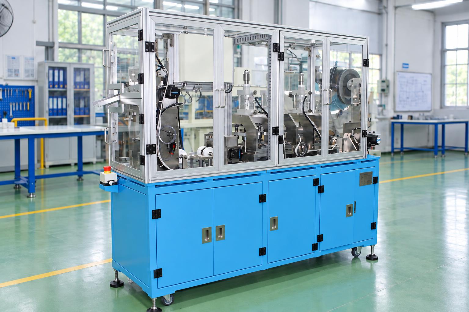
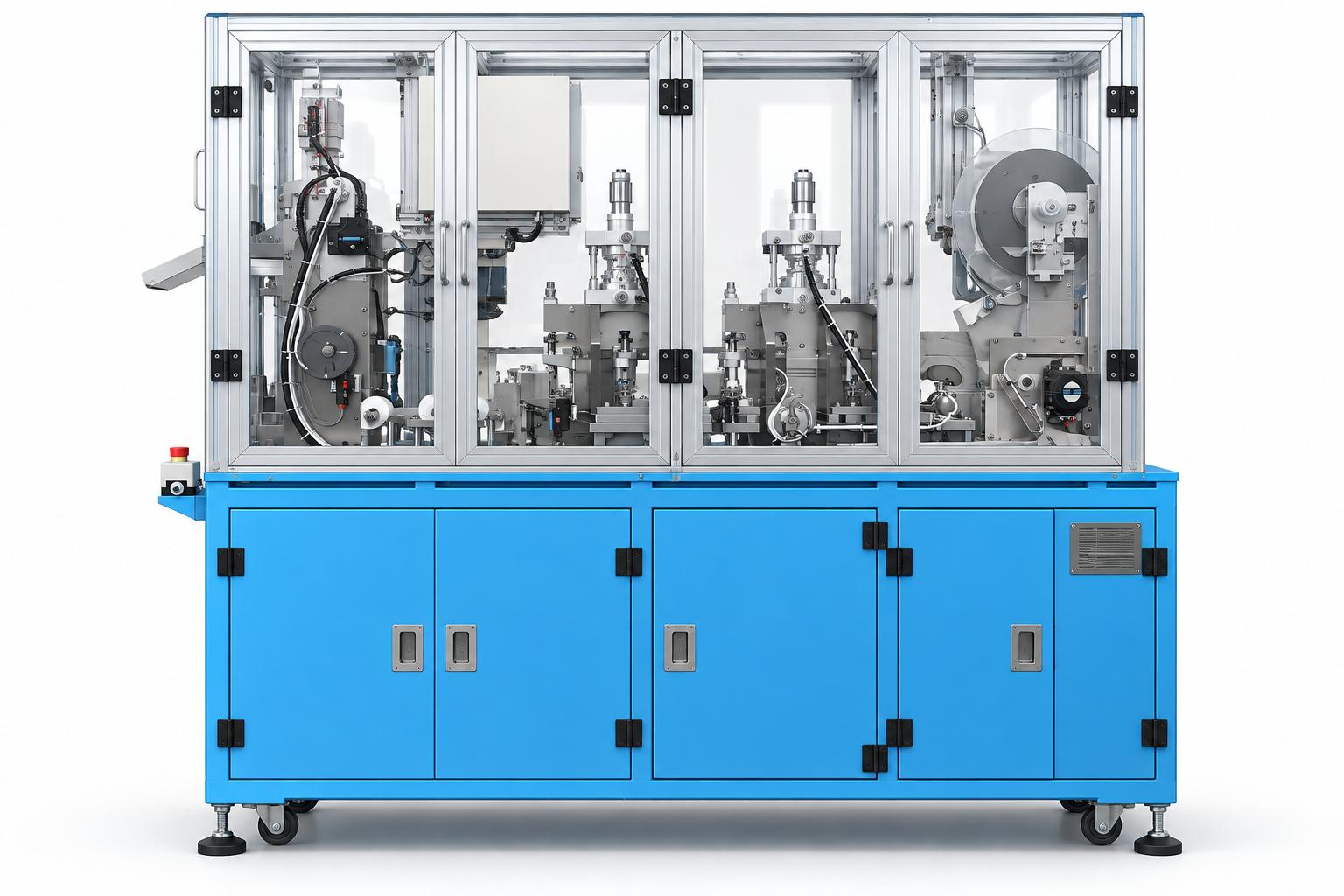
Automatic cable punching machine integrates roll-fed material feeding, servo-driven cable pulling, die punching, and cutting to length into a single system. The machine is equipped with three pneumatic punching units, two servo-driven pulling axes, and a programmable cutting unit. A PLC coordinates the machine's operations, while the HMI touchscreen allows operators to select punching tool combinations, configure motion parameters, and save product settings. The machine is suitable for processing cable strips supplied from rolls that require holes or specific profiles to be punched before being cut to predetermined lengths. Integrating these operations into one system simplifies production setup and product configuration management. The applicable processing range must be verified based on the material, technical drawings, punching dies, and actual guiding mechanism.
VIETNAM CNC & TECHNOLOGY APPLICATION JOINT STOCK COMPANY
Hotline: +84.916 63 9355 / +84.915 74 4664
Email: Sales01@cncvina.com.vn / Sales03@cncvina.com.vn
Product description

Automatic cable punching machine integrates roll-fed material feeding, servo-driven cable pulling, die punching, and cutting to length into a single system. The machine is equipped with three pneumatic punching units, two servo-driven pulling axes, and a programmable cutting unit. A PLC coordinates the machine's operations, while the HMI touchscreen allows operators to select punching tool combinations, configure motion parameters, and save product settings. The machine is suitable for processing cable strips supplied from rolls that require holes or specific profiles to be punched before being cut to predetermined lengths. Integrating these operations into one system simplifies production setup and product configuration management. The applicable processing range must be verified based on the material, technical drawings, punching dies, and actual guiding mechanism.
What is an automatic cable punching machine?
An automatic cable punching machine is a device designed to feed cable strips from rolls, position the material, punch holes using dedicated dies, and cut the processed material into specified lengths. The system can integrate servo drives, pneumatic mechanisms, and PLC control to coordinate machining operations and meet requirements for hole positioning, profile geometry, and finished product length.
Role of the machine in the production process
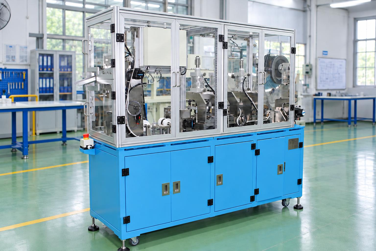
In cable processing, hole positions and cut lengths must be controlled according to product drawings. When punching and cutting operations are integrated into a single system, cable feeding movements, punching strokes, and cutting timing can be coordinated through a unified control sequence.
CNC VINA's automatic cable punching machine features two separate pulling sections for punching and cutting, with guide rollers and a cable buffer section between the processing stages. Sensors monitor roller positions and provide signals for operating conditions, helping coordinate material feeding and pulling movements. In manufacturing facilities, the machine can be used to prepare cable strips before assembly or transfer to subsequent production stages. Product quality should be evaluated based on hole positioning, punched profile geometry, cut length, and material condition after processing. Actual productivity depends on die configuration, material properties, feeding and cutting cycles, and production setup time.
Key features of CNC VINA's automatic cable punching machine
- Roll-fed cable feeding and integrated processing: Combines material feeding, pulling, punching, and cutting operations within a single system.
- Three die punching units: Punching units are arranged according to product drawings and machining programs.
- Two servo-driven cable pulling axes: Control movements in the punching and cutting sections, allowing operators to configure positioning and speed parameters through the HMI.
- Pneumatically actuated punching and cutting mechanisms: Pneumatic cylinders drive the punching dies and cutting blade according to the programmed operating sequence.
- Storage for 50 product parameter sets: Allows previously configured settings to be recalled during production preparation.
- HMI monitoring: Displays operating status, cycle time, production count, and alarm history.
- Preset quantity operation: Supports production runs based on specified quantities.
These features represent the machine's reference configuration. Processing capability for each cable type must be verified through material samples, die sets, material guiding arrangements, and trial-run results.
Structure and technology of the automatic cable punching and cutting machine
Roll feeding and material guiding unit
The cable roll is mounted at the machine inlet. The material then passes through the feeding mechanism and guide rollers before entering the punching section. A material depletion sensor monitors cable availability at the inlet. Guide rollers and the cable buffer section between processing stations help coordinate pulling movements during operation. Stable material feeding depends on proper roll installation, cable routing, and roller pressure conditions. When preparing a new product, operators should check the feeding direction, material straightness, and surface condition after the cable passes through the guiding mechanism. Excessive tension, slack, or misalignment must be avoided.
Two servo-driven cable pulling axes
Two servo axes control cable pulling movements in the punching and cutting sections. Operators configure positioning and pulling speed parameters through the HMI according to the validated machining program. The PLC uses these parameters, together with sensor signals and operating interlocks, to coordinate the processing sequence. Position parameters determine cable displacement and programmed processing locations. When hole dimensions or profiles change, suitable punches and dies must be selected. When punching positions change, motion settings, material guiding arrangements, and actual sample results must be rechecked. A registration mark sensor detects reference marks on the cable and provides positioning signals during each cycle. When changing materials or cable routing arrangements, the reliability of reference mark detection must be verified. Positioning accuracy must be confirmed through measurements of finished products rather than relying solely on servo operating status.
Three pneumatically actuated mechanical punching units
Each punching unit consists of a pneumatic cylinder and a die set comprising a punch, die, and guiding mechanism. Once the cable reaches the required position and operating conditions are satisfied, the cylinder performs the programmed punching stroke. The punching tool combination selected on the HMI determines which units participate in the processing cycle. Hole geometry and dimensions depend on the installed die set. Product changeovers may require replacing punches and dies and adjusting the cable guiding mechanism. After die installation, alignment, operating positions, and sample quality must be checked before production begins.
The three punching units allow multiple processing positions along the material path. However, the number of holes per product and the punching sequence must be determined according to product drawings, die configuration, and machining programs. These parameters cannot be inferred solely from the number of installed punching units.
Cable pulling and cutting unit
After punching, the cable passes through a supporting mechanism and enters the cutting section. The servo axis in this section works together with the material holding mechanism and pneumatic cutting cylinder to cut the cable into segments according to the configured parameters. During product preparation, the required cut length, hole positions relative to the cut ends, and cut-edge quality requirements must be defined. The cutting blade, holding mechanism, and material guiding path must be suitable for the cable material to minimize displacement or deformation beyond acceptable limits. Processed products are collected according to the station's operating cycle.
PLC control system and HMI touchscreen
The PLC manages operating sequences, step transition conditions, and sensor feedback signals. The HMI touchscreen supports manual and automatic operation, punching tool combination selection, and configuration of pulling, punching, and cutting parameters. Manual mode allows operators to inspect individual mechanisms before conducting product trial runs. The HMI provides 50 parameter storage slots, allowing previously configured product settings to be saved and recalled. This function facilitates repeated production runs but does not eliminate the need to inspect dies, guiding mechanisms, and product samples when materials or mechanical configurations change. The HMI displays machine status, operating conditions of individual mechanisms, cycle time, production count, and alarm history. Preset quantity operation supports production progress monitoring. The recorded production count must be distinguished from the number of products that meet quality requirements.
Sensors and safety mechanisms
Sensors along the cable path, cylinder position sensors, and door switches provide feedback signals to the control system. Depending on the machine configuration, alarms may indicate material depletion, open safety doors, incorrect cylinder positions, or roller positions exceeding permitted limits. The machine is equipped with protective enclosures around the processing area, an emergency stop button, status indicator lights, and an audible alarm according to its configuration. When an alarm occurs, operators must identify the cause and restore the machine to an appropriate operating condition before restarting.
During die replacement or troubleshooting inside the machine, electrical and pneumatic energy sources must be isolated in accordance with the factory's applicable safety procedures.
Reference technical specifications
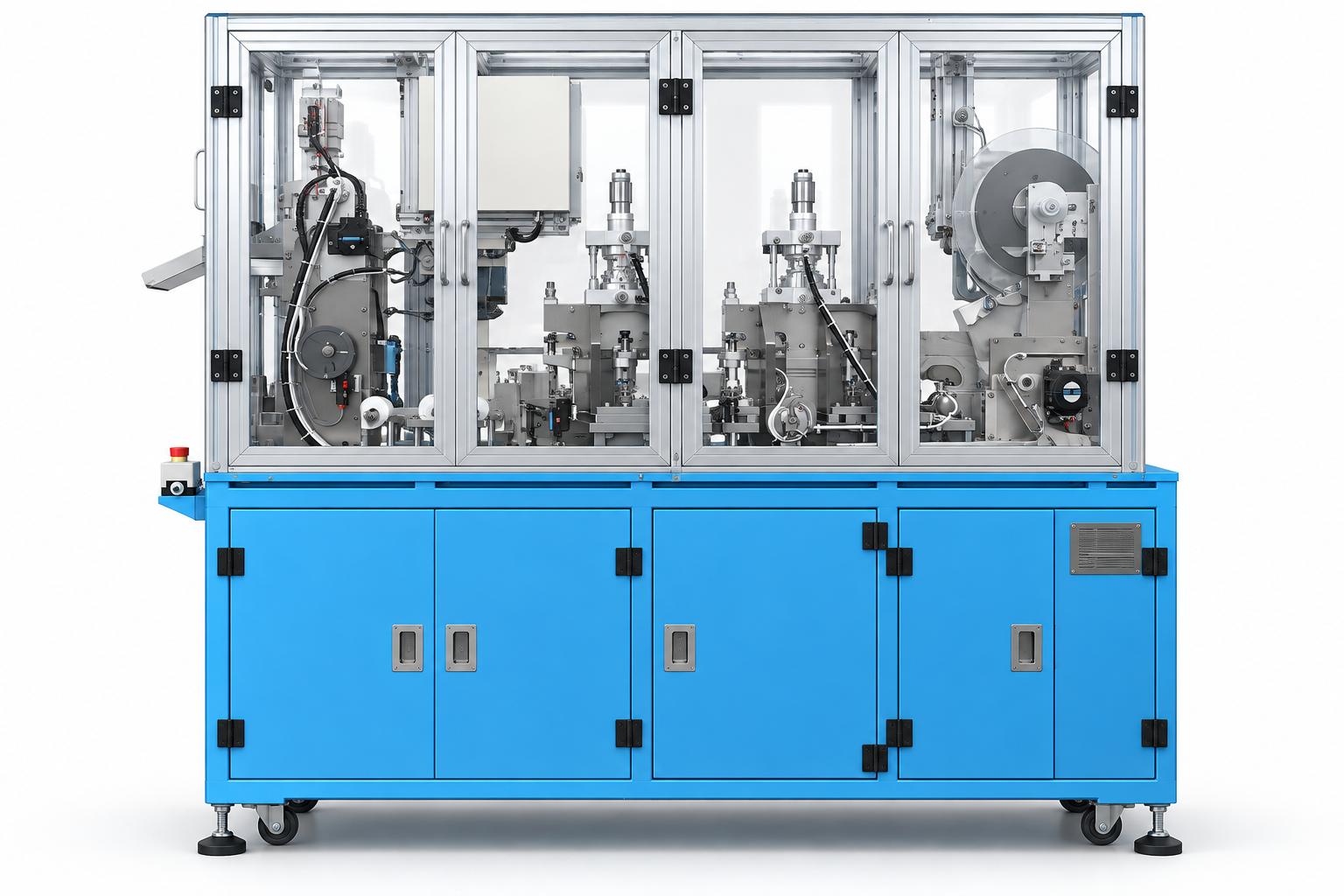
| Item | Reference specifications |
|---|---|
| Input material | Roll-fed cable strips |
| Integrated operations | Feeding, pulling, punching, and cutting to length |
| Number of punching units | 3 units |
| Punching mechanism | Pneumatic cylinders with punch and die sets |
| Cutting mechanism | Pneumatically actuated cutting blade |
| Cable pulling drive | 2 servo axes for the punching and cutting sections |
| Control system | PLC and HMI touchscreen |
| HMI parameter storage | 50 parameter sets |
| Operation monitoring | Operating status, cycle time, production count, and alarm history |
| Main power supply | AC 220 V, single-phase |
| Control power supply | DC 24 V |
| Compressed air pressure | 0.4–0.6 MPa |
| Reference operator requirement | 1 operator |
| Reference working height | 900 mm from floor level |
The above specifications represent the machine's reference configuration and must be verified against the equipment documentation before finalizing the technical solution. Material width and thickness, hole dimensions, cutting length, production cycle time, and tolerance requirements must be confirmed based on material samples, die sets, and trial-run results.
The installation layout must also provide sufficient space for roll replacement, maintenance door access, finished product collection, and die handling.
Operating principle of the automatic cable punching machine
The processing sequence is controlled according to the programmed operating logic and material conditions along the feeding path. The basic operating steps include:
-
Roll and cable path preparation: Install the cable roll, thread the cable strip through the guiding mechanisms, and inspect the rollers and material condition.
-
Die and parameter setup: Verify the punches, dies, cutting blade, guiding mechanisms, selected punching tool combinations, and configured processing parameters.
-
Machine initialization: Check the electrical power supply, compressed air supply, safety doors, and mechanism status. Return the system to its home position according to the operating instructions.
-
Cable feeding and pulling: The feeding mechanism and servo axes move the material to the programmed processing positions when the required operating conditions are satisfied.
-
Punching operation: The selected punching units perform their operations in the programmed sequence, after which the cable advances according to the configured settings.
-
Cable pulling and cutting: The pulling mechanism in the cutting section works together with the material holding mechanism and cutting blade to separate the finished cable segments.
-
Monitoring and product collection: The operator monitors machine status, responds to alarms, collects processed products, and performs quality inspections according to the production plan.
Before starting continuous automatic operation, sample processing must be performed under suitable conditions to verify both hole positions and cutting lengths. After die replacement, configuration changes, or abnormal operating conditions, product quality must be rechecked before production resumes.
Applications in industrial man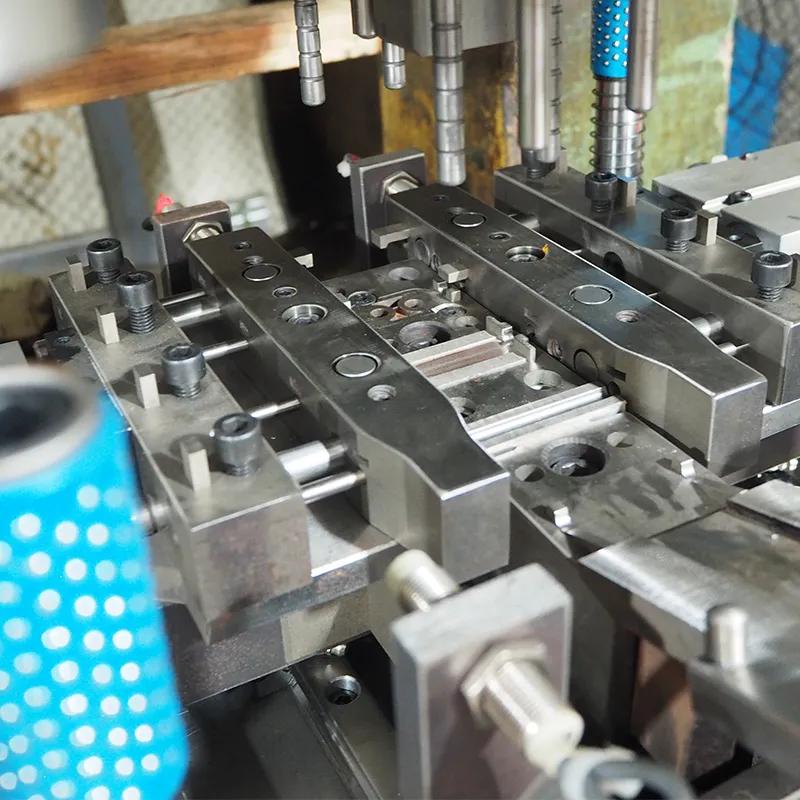
Processing roll-fed cable strips
The automatic cable punching and cutting machine can process roll-fed cable strips into segments with holes or specific profiles according to product drawings. Integrating feeding, pulling, punching, and cutting operations allows these processes to be performed within a single system. The material must be compatible with the designed roller mechanisms, guiding system, and die sets.
Repeated batch production
For products with stable configurations, operators can recall saved parameter sets, inspect the dies, and verify the first sample of each batch before starting production based on the preset quantity. This approach supports consistent configuration management across production batches. However, inspection procedures remain necessary when replacing material rolls or adjusting mechanical components.
Preparing cable components for assembly
The machine can be considered for processing cable components that require holes or specific profiles for positioning, assembly, or connection with other parts. For cables containing conductive elements, the permitted punching and cutting areas must be clearly defined. Structural integrity requirements must also be verified against product drawings.
Custom processing of technical strip materials
In addition to cables, certain technical strip materials may be considered for processing if they meet the requirements of the pulling mechanism, punching dies, and cutting blade. Processing capability depends on material properties, width, thickness, required punching force, and edge quality. Sample testing is necessary to verify feasibility before finalizing the machine configuration.
Selection criteria for a cable punching and cutting machine
Material specifications and permitted processing areas
Material samples or technical drawings should be provided, together with information on material type, width, thickness, and roll-feeding method. The permitted punching areas, sections that must remain intact, edge quality requirements, and post-processing methods must also be defined. These specifications provide the basis for selecting suitable dies, rollers, and material guiding arrangements.
Relationship between hole positions and cut edges
Hole positions must be defined according to the product's measurement references, such as the distance from a cut end or a registration mark on the cable strip. Inspection criteria should include hole geometry, spacing between processing positions, and the final cut length. Positioning methods based on servo-driven pulling movements or sensor signals must be verified as part of the control system design. Actual processed products must be measured to evaluate compliance with technical requirements.
Die replacement and product changeover capability
When changing products, the punches, dies, and cutting blade must be inspected, and the material guiding mechanism adjusted as required. Operators then recall the corresponding parameter set and verify the selected punching tool combination, pulling positions, and speeds. The first product after a configuration change must be measured and inspected before starting production at the preset quantity.
Production cycle time and data requirements
The processing cycle time depends on the number of punching operations, pulling distance, cutting cycle, and material feeding conditions. The cycle time displayed on the HMI supports operation monitoring. However, production planning must also account for roll replacement, sample inspection, and die maintenance. If the factory requires automatic inspection, product sorting, or data integration with a manufacturing execution system (MES), these functions must be specified separately within the machine design scope. They should not be assumed to be included in the standard configuration.
Sample testing and machine acceptance
Sample testing is an essential step in evaluating whether the automatic cable punching machine meets actual processing requirements. Representative material rolls, along with the punching dies and cutting blades intended for production, should be used during testing.
Key inspection criteria include:
- Hole positions, geometry, and dimensions.
- Distances between processing positions.
- Cut length and cut-edge condition.
- Burrs, scratches, or material deformation.
- Complete separation of cut segments and stability of the cable feeding path.
- Processing results after roll replacement or loading a different configuration.
Operational acceptance testing must verify material feeding, operating interlocks, punching and cutting sequences, sensor feedback, and preset quantity operation. Alarms included in the actual machine configuration must also be tested according to the agreed commissioning and handover procedures. Sample testing results provide the basis for defining the applicable material range, product quality criteria, and operating cycle time. Acceptance limits must be agreed upon by all relevant parties before final machine acceptance.
Operation and maintenance
Before operation, the cable roll, material feeding path, rollers, punching dies, cutting blade, electrical power supply, and compressed air supply must be inspected. Operators should verify the selected configuration, machine home position, and readiness conditions according to the operating instructions. During production, cable feeding conditions, hole quality, and finished product lengths must be monitored. If an alarm occurs or an abnormal product is detected, the machine must be stopped according to the established procedure to identify the cause before operation resumes.
Maintenance focuses on the sharpness and alignment of punches and dies, cutting blade condition, guiding mechanisms, rollers, pneumatic components, and sensors. Material scraps must be removed from the processing area according to maintenance instructions to prevent interference with the dies and cable feeding path. During die replacement, jam removal, or internal machine maintenance, electrical and pneumatic energy sources must be shut off and isolated in accordance with applicable safety procedures. The machine may only be restarted after the work area has been inspected and all mechanisms have been confirmed to be in a safe operating condition.
Frequently asked questions about automatic cable punching machines
Which operations does the machine perform automatically?
The machine coordinates material feeding, pulling, punching, and cutting operations according to the programmed sequence after setup and startup. Operators remain responsible for roll installation, cable threading, die replacement, adjustments, product collection, and quality inspection. Automatic roll replacement or packaging functions must be considered separately if required.
Can hole dimensions be changed using only the HMI?
Hole geometry and dimensions depend on the punches and dies installed in the machine. The HMI allows operators to configure motion parameters and processing positions according to the program. Changing hole dimensions may require die replacement, while changing hole positions requires verification of motion settings, material guiding arrangements, and actual processed samples.
Do three punching units produce exactly three holes per product?
Not necessarily. The number of holes and the combination of activated punching units depend on product drawings, die configuration, and the control program. The number of installed punching units does not directly determine the number of holes in each product.
Does storing 50 parameter sets mean the machine can process 50 different cable types?
The HMI provides 50 storage slots for product configurations. However, the ability to process different cable types depends on material properties, punching dies, guiding mechanisms, and pulling systems. Each configuration must be verified through sample testing after the appropriate mechanical setup has been completed.
Does the production counter confirm that all products meet quality requirements?
The production counter tracks the number of products processed during operation but does not replace quality inspection. Hole positions, geometry, cut lengths, and material conditions must be evaluated according to the applicable process quality criteria. If automatic inspection and sorting are required, a suitable inspection system must be incorporated into the machine design.
CNC VINA designs custom automatic cable punching machines
CNC VINA's automatic cable punching machine integrates roll feeding, servo-driven cable pulling, die punching, and cutting to length within a single system. The machine configuration can be customized according to material properties, product drawings, hole positions, cutting lengths, and the factory's production cycle requirements.
CNC VINA can develop punching dies, material guiding mechanisms, drive systems, and control solutions based on agreed technical specifications. Before project implementation, manufacturers are encouraged to provide cable samples or technical drawings to evaluate processing feasibility and establish machine acceptance criteria.
VIETNAM CNC & TECHNOLOGY APPLICATION JOINT STOCK COMPANY
Factory: Song Cung Industrial Cluster, Dong Thap Commune, Dan Phuong District, Hanoi, Vietnam.
Office: Rox Tower Goldmark City, 136 Ho Tung Mau Street, Phu Dien Ward, Hanoi, Vietnam.
Phone: +84 916 639 355 / +84 915 744 664
Website: www.cncvina.com.vn ; www.cncvina.net