 Tiếng
Việt
Tiếng
Việt
 Tiếng
Anh
Tiếng
Anh
 Tiếng
Nhật
Tiếng
Nhật




 Tiếng Anh

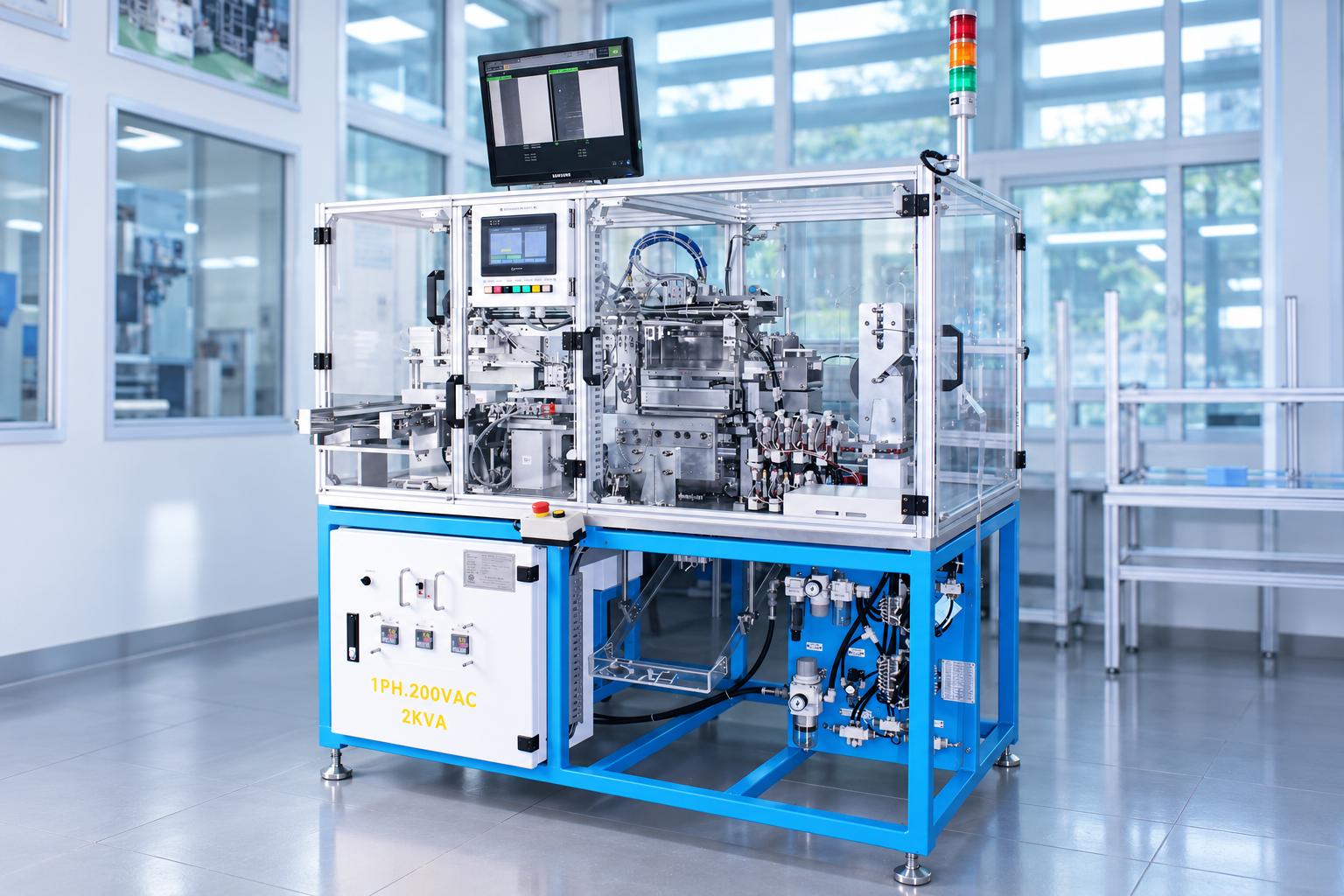
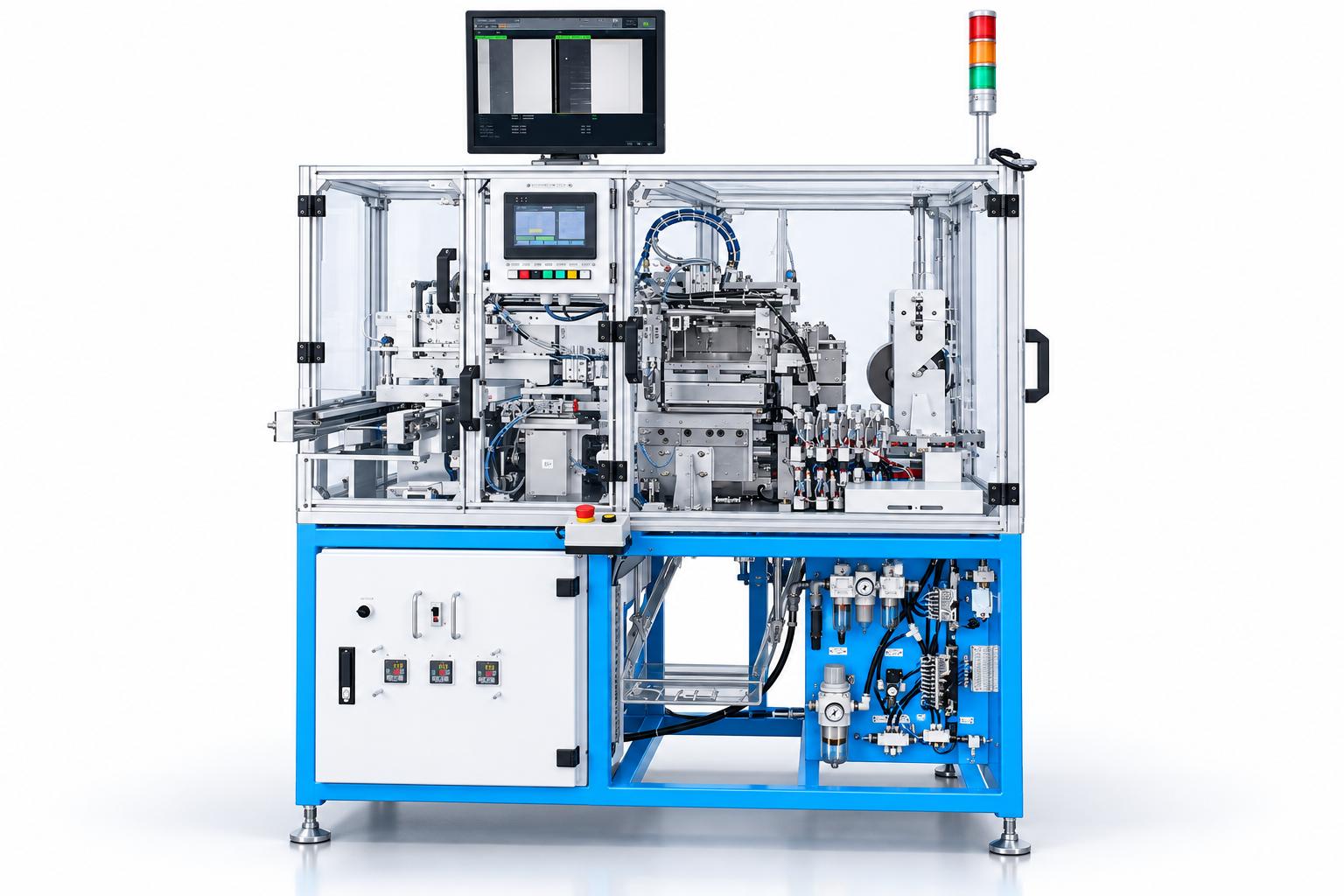
Automatic cable protective film laminating machine
Automatic cable protective film laminating machine is designed to automatically feed, cut, and apply protective film to cable products. The system integrates a camera-based length measurement unit and product transfer mechanisms to move cables between processing stations. After film application, the cables undergo heat pressing and heated roller smoothing before being transferred to the output tray. This configuration is suitable for batch cable production where precise control of film length, application position, and adhesion quality is required. Operators prepare the cable trays, film rolls, and production settings, while the machine automatically performs cable transfer, film feeding, cutting, lamination, and product unloading.
VIETNAM CNC & TECHNOLOGY APPLICATION JOINT STOCK COMPANY
Hotline: +84.916 63 9355 / +84.915 74 4664
Email: Sales01@cncvina.com.vn / Sales03@cncvina.com.vn
Product description

Automatic cable protective film laminating machine is designed to automatically feed, cut, and apply protective film to cable products. The system integrates a camera-based length measurement unit and product transfer mechanisms to move cables between processing stations. After film application, the cables undergo heat pressing and heated roller smoothing before being transferred to the output tray. This configuration is suitable for batch cable production where precise control of film length, application position, and adhesion quality is required. Operators prepare the cable trays, film rolls, and production settings, while the machine automatically performs cable transfer, film feeding, cutting, lamination, and product unloading.
Role of the automatic cable protective film laminating machine in production
In cable manufacturing, protective film application requires accurate coordination of material length, cable positioning, and lamination conditions. Improper cable positioning may cause the film to shift away from the intended protection area. Unstable film feeding can affect cutting length, while unsuitable temperature and pressing conditions may reduce adhesion quality or cause product deformation. CNC VINA's automatic cable protective film laminating machine integrates these operations into a single automated system. Fixtures and vacuum suction heads secure and transfer cables at the processing stations. The camera provides length measurement data to the film feeding mechanism, while the heat-pressing and heated roller units complete the lamination process according to preset parameter
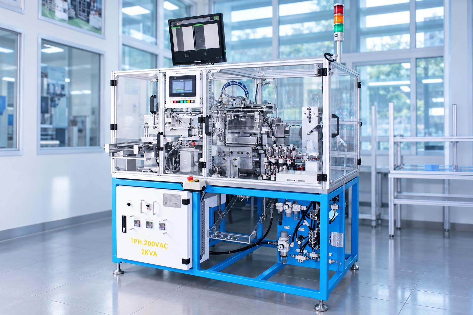
The coordinated operation of these mechanisms reduces manual product transfers between processing stages while enabling more consistent control of the film lamination sequence in batch production. Operators can monitor machine status, cycle time, production counts, and alarms through the control panel.
The machine can be installed at the protective film lamination stage before cables proceed to inspection or subsequent assembly. Its application scope depends on cable dimensions, film material, lamination area, and the product's heat resistance. CNC VINA can evaluate actual product samples to determine suitable film feeding, positioning, and heat-pressing solutions.
Key features of the automatic cable protective film laminating machine
-
Camera-based cable length measurement: Provides measurement data for determining film feeding and cutting positions.
-
Position-controlled film pulling mechanism: Coordinates film gripping, pulling, cutting, and application according to the measured cable length.
-
Servo-driven rotary indexing unit: Transfers cables between processing stations using dedicated fixtures.
-
Vacuum-assisted cable handling: Uses vacuum suction heads and pneumatic cylinders at the infeed, intermediate transfer, rotary, and outfeed stations.
-
Heated lamination, pressing, and roller smoothing: The control system monitors the temperature-ready status of the relevant heating units.
-
Touchscreen HMI and PLC: Support product selection, parameter settings, cycle monitoring, production counters, and fault notifications.
-
Product-specific interchangeable fixtures: Allow adjustments to suction head positions, camera alignment, and film feeding paths when changing product models.
Machine structure and technology
Cable feeding and vacuum transfer system
Cables are arranged in trays on the infeed conveyor. Lifting and transfer mechanisms equipped with vacuum suction heads pick up, hold, and move the products to subsequent stations. Fixtures and positioning points maintain proper cable orientation during transfer to the intermediate and rotary units. Suction head positions can be adjusted according to cable length. Suction heads not required for a particular product must be configured appropriately to maintain sufficient vacuum holding performance. When selecting the machine, cable flatness, rigidity, and surface characteristics should be evaluated to determine suitable support and gripping methods and prevent misalignment during transfers.
Camera-based length measurement and film pulling coordination
The camera measures cable length before the lamination process. The control system uses this data to determine the required film length and the operating positions of the film pulling mechanism. The mechanical positioning of the camera unit can also be adjusted for different product types. This measurement function enables film feeding based on actual cable dimensions rather than a fixed pulling length. The system generates an alarm when the measured length falls below the permissible limit. During acceptance testing, measurement results should be verified against reference samples with known dimensions, including samples close to the acceptance limits. The camera inspection scope must be defined for each project. Cable length measurement and post-lamination film quality inspection are separate functions. If additional inspection of film misalignment, wrinkles, or uncovered areas is required, a corresponding inspection solution must be designed.
Film roll feeding and material guiding system
The film feeding unit consists of a material roll, rollers, and guiding mechanisms. Guide pin positions are adjusted to accommodate the film width required for each product type. Separate paths are provided for incoming film and excess material. Proper film routing ensures stable material feeding into the gripping and cutting units. During roll replacement, operators should check the threading direction, roller condition, and excess material path before resuming production. Film width, adhesive layer characteristics, and heat resistance must be compatible with the cable and the required finished-product specifications.
Film pulling, cutting, and lamination unit
The film pulling mechanism moves to preset gripping, pressing, and cutting positions. Cable length data obtained from the camera is used to determine the operating positions associated with the required film length. The cutting unit separates the film, while the pressing mechanisms bring the material into contact with the cable. Blade condition and film holding stability directly affect cutting-edge quality. During machine trials, the film should be checked for complete cutting, edge stretching or tearing, and correct positioning on the product. Cutting and lamination performance should be evaluated on the same sample to verify coordination between the mechanisms.
Rotary indexing, heat pressing, and heated roller smoothing units
The rotary indexing unit features four fixture positions, transferring cables through successive processing stages. The film is bonded to the cable through heat-assisted pressing, followed by additional heat pressing and heated roller smoothing before the finished product is transferred to the output tray. Temperature, pressing time, and contact alignment must be established according to the film and cable materials. For the roller unit, roller height directly affects the result. If positioned too high, the roller may not provide sufficient contact for proper film adhesion. If positioned too low, it may push the cable sideways and cause misalignment. This adjustment requires particular attention during machine setup and product changeovers.
PLC, touchscreen HMI, and operating interlocks
The PLC coordinates cable transfer, rotary indexing, film pulling, cutting, and heating operations. The touchscreen HMI displays the home-position status of individual units, door-closed status, temperature-ready conditions, and machine operating status. Operators can monitor film length, cycle time, input and output counters, and fault history. The output counter records products that have completed the operating cycle; product quality must be verified against the agreed inspection criteria. Parameter settings support adjustments to operating positions, speeds, pressing times, and output tray quantity settings. Product selection functions allow the corresponding parameter set to be recalled, although mechanical components may still require replacement or adjustment during changeovers.
Operating principle of the automatic cable protective film laminating machine
Before operation, the operator prepares the cable trays, film roll, and appropriate fixtures, returns the mechanisms to their home positions, and selects the required product model. For automatic operation, AUTO mode must be selected, the drives enabled and confirmed ready, the safety doors closed, and the heating units at their required operating temperatures.
Cable feeding from trays: The infeed mechanism picks up and transfers cables to the measurement area, maintaining proper orientation using vacuum suction heads and fixtures.
Cable length measurement: The camera measures cable length, allowing the control system to determine the required film pulling length and related operating positions.
Transfer to the rotary indexing unit: Intermediate transfer mechanisms move the cable to a fixture at the processing unit.
Film pulling, cutting, and lamination: The pulling mechanism feeds the required film length and coordinates cutting and heat-assisted pressing operations.
Heat pressing and roller smoothing: The cable passes through subsequent processing units to achieve the required adhesion and surface flatness.
Product unloading: The outfeed mechanisms transfer completed cables to the output tray while the control system updates the production counter.
When completing a production batch or changing product models, the cycle completion function allows the machine to finish processing the cables already in the operating sequence before returning to its home state. This procedure should be coordinated with infeed preparation to prevent different product models from being mixed.
Industrial applications
Protective film lamination in cable manufacturing: This is the primary application of the machine configuration described. The system applies protective film to cables with dimensions and orientations compatible with its trays, fixtures, and vacuum suction heads. Camera-based measurement supports film length determination, while the lamination, heat-pressing, and heated roller units ensure contact between the film and cable. Compatibility must be verified using the specified film material and product quality standards.
Preparation of cable connection components for electronic assembly: For cables requiring protective film in designated areas before assembly, the system can be configured according to the required lamination and clearance zones. The machine integrates film application into a controlled process, preparing the products for subsequent assembly. The effects of heat and holding mechanisms on functional cable components must be evaluated.
Cable production for home appliances and automotive auxiliary systems: Where heat-assisted film lamination is required, CNC VINA can evaluate suitable fixture designs, film feeding arrangements, and product transfer mechanisms. Application feasibility depends on stable cable positioning, accessibility of the lamination area, and successful validation against project-specific requirements. Compliance with industry-specific standards must be verified using actual products.
Film lamination for other thin components upon request: The principles of length measurement, controlled material feeding, and heat-assisted pressing may also be considered for certain other products. Feeding mechanisms, fixtures, and pressing conditions must be redesigned according to component geometry, rigidity, and material properties. Wide sheets or applications requiring lamination over large surface areas may require a dedicated machine configuration rather than direct use of the cable laminating system.
Reference technical specifications of the automatic cable protective film laminating machine
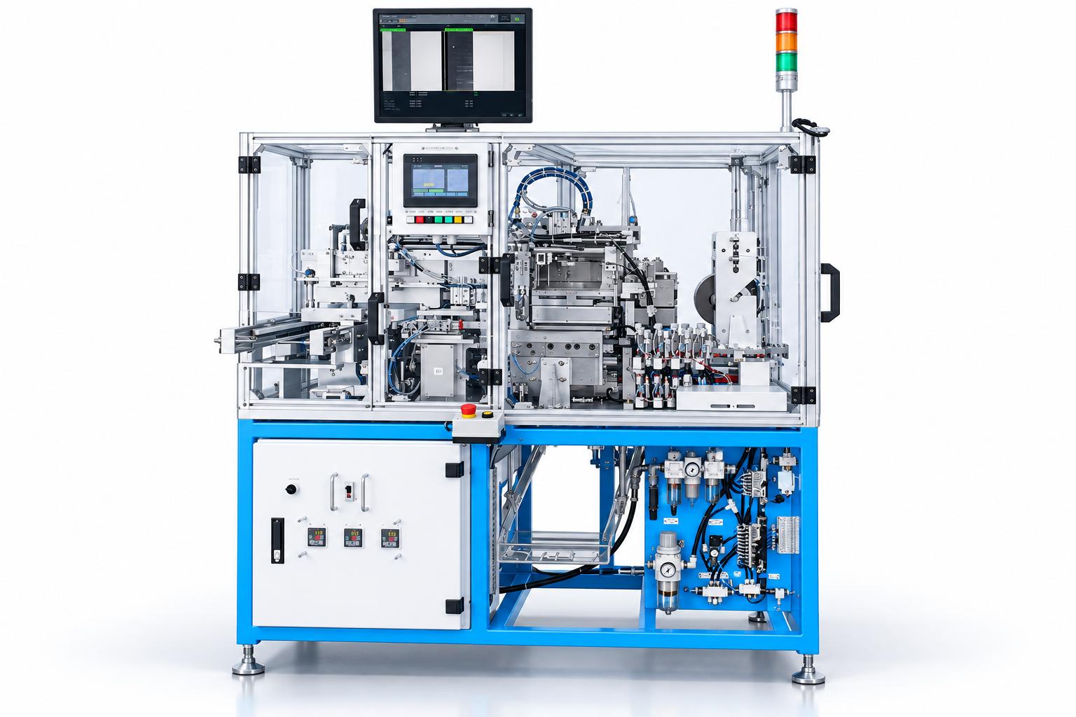
Reference technical specifications of the automatic cable protective film laminating machine
| Item | Reference specification |
|---|---|
| Product handling | Cables fed and transferred using trays, fixtures, and vacuum suction heads |
| Cable width | 8–38 mm |
| Cable length | 45–450 mm |
| Reference design cycle time | 9 seconds/product |
| Designed operator requirement | 1 operator |
| Rotary indexing unit | 4 fixture positions |
| Measurement technology | Camera-based cable length measurement |
| Lamination technology | Film pulling and cutting, combined with heat-assisted pressing and heated roller smoothing |
| Product holding and transfer | Vacuum suction combined with pneumatic mechanisms |
| Compressed air supply | 0.4–0.6 MPa |
| Control voltage | DC 24 V |
| Control system | PLC, touchscreen HMI, servo drives, and position-controlled film pulling mechanism |
The cable width and length ranges above apply to the reference machine configuration. Film dimensions, fixtures, and pressing conditions are determined separately according to the product. The 9-second cycle time must be verified under actual tray loading conditions, material characteristics, and output quality requirements before being used for production planning.
Key factors to consider when selecting the machine
Product specifications and lamination area: Provide cable samples or technical drawings showing length, width, thickness, required film application areas, and areas that must remain uncovered. Components susceptible to deformation or unsuitable for contact with handling mechanisms should be identified during fixture design.
Film material: Specify roll width, adhesive layer structure, feeding direction, and requirements for subsequent use. If the film must be removed in a later process, peelability and potential adhesive residue should be evaluated. If the film remains on the product as a protective layer, appropriate adhesion criteria must be established.
Heating and pressing conditions: Define acceptance criteria for adhesion, wrinkles, lifted edges, and cable deformation. Temperature, pressing time, and roller position should be evaluated together to determine suitable processing conditions for both the film and cable.
Inspection requirements: Determine which dimensions the camera must measure, acceptable tolerances, and how out-of-tolerance results should be handled. If additional post-lamination inspection or integration with electrical testing equipment is required, these functions must be included in the design scope.
Production throughput: Evaluate tray preparation, film roll replacement, fixture changeovers, and first-piece inspection time in addition to the machine cycle time. Effective production output is determined by the number of acceptable products, so quality results and production downtime must also be considered.
Sample testing and evaluation before handover
Testing should be conducted using the actual cable and film materials intended for production, including representative product sizes within the required range. Results should be evaluated throughout the entire process, from cable feeding to output tray unloading, to identify the causes of any defects.
- Cable feeding and transfer: Verify product pickup from trays, vacuum holding performance, and correct positioning on each fixture.
- Measurement and film feeding: Compare camera measurements with reference sample dimensions, check cut film lengths, and evaluate consistency across repeated feeding cycles.
- Post-lamination quality: Inspect film positioning, coverage, wrinkles, lifted edges, adhesion, and cable condition after heat pressing.
- Cutting and roller smoothing: Confirm complete cutting, absence of film tearing or stretching, and stable cable positioning during roller smoothing.
- Batch operation: Check input and output counters, cycle time, full-tray conditions, film roll replacement, and first-piece quality after product changeovers.
- Control functions: Verify homing conditions, door-closed interlocks, temperature-ready status, fault alarms, and emergency stop functions.
Acceptance limits should be agreed upon before testing. If peel strength, adhesion after storage, or special operating conditions are required, appropriate test methods and inspection timing must be established.
Operation and maintenance
Before each shift, operators should inspect the trays, fixtures, suction heads, film path, cutting unit, and heating unit status. First-piece inspection at the beginning of each shift helps identify changes in film positioning, cutting-edge quality, or roller smoothing performance before batch production begins. Key inspection points include vacuum line integrity, suction head condition, cutting blades, rollers, guide components, pneumatic cylinders, and sensors. Contact surfaces should be cleaned according to appropriate procedures, and maintenance oils or grease must be kept away from cutting blades, film materials, and lamination areas. When a fault occurs, its cause should be identified before clearing the alarm and restarting the machine. Fixture replacement, blade replacement, or internal adjustments must only be performed after the machine has been stopped, energy sources isolated, and heated components brought to a safe condition in accordance with established procedures. These tasks must be carried out by authorized personnel.
Frequently asked questions about the automatic cable protective film laminating machine
Which operations does the machine perform automatically?
The system automatically picks up and transfers cables, measures cable length, pulls and cuts film, performs lamination, heat pressing, and roller smoothing, and transfers completed products to the output tray. The operator prepares products and materials, selects the appropriate configuration, monitors operation, and performs product changeovers according to established procedures.
Does the camera inspect overall product quality?
In this configuration, the camera primarily measures cable length to support film pulling and cutting operations and provides alarms related to measurement limits. Inspection of post-lamination film positioning, adhesion, or electrical quality requires corresponding inspection methods and equipment if specified by the project.
Can different cable models be processed simply by selecting a product type on the touchscreen?
Selecting a parameter set on the touchscreen must be accompanied by compatible fixtures, trays, suction head positions, and film routing. Changing cable models may require multiple mechanical adjustments, followed by trial operation and first-piece approval before full production resumes.
Can this machine laminate protective film onto wide sheets?
The reference configuration is designed for cables with dimensions compatible with its tray and fixture system. For wide sheets, different materials, or larger lamination areas, CNC VINA can evaluate a dedicated solution for product feeding, film guiding, and pressing mechanisms.
CNC VINA – Custom machine design and manufacturing
CNC VINA provides custom design and manufacturing services for protective film laminating machines based on product specifications, material types, lamination areas, and production throughput requirements. Machine configurations can be adapted in terms of fixtures, cable feeding systems, film routing, pulling and cutting mechanisms, heat-pressing conditions, and inspection requirements. For production line integration, product transfer arrangements and control signal interfaces are defined according to the connected processes. Sample testing and agreement on output quality standards provide the basis for selecting the appropriate machine configuration, evaluating application feasibility, and preparing the production solution.
Businesses are welcome to submit product information and film lamination requirements for CNC VINA to evaluate a suitable technical solution.
VIETNAM CNC & TECHNOLOGY APPLICATION JOINT STOCK COMPANY
Factory: Song Cung Industrial Cluster, Dong Thap Commune, Dan Phuong District, Hanoi, Vietnam.
Office: Rox Tower Goldmark City, 136 Ho Tung Mau Street, Phu Dien Ward, Hanoi, Vietnam.
Tel: +84 916 639 355 / +84 915 744 664
Websites: www.cncvina.com.vn ; www.cncvina.net