 Tiếng
Việt
Tiếng
Việt
 Tiếng
Anh
Tiếng
Anh
 Tiếng
Nhật
Tiếng
Nhật




 Tiếng Anh

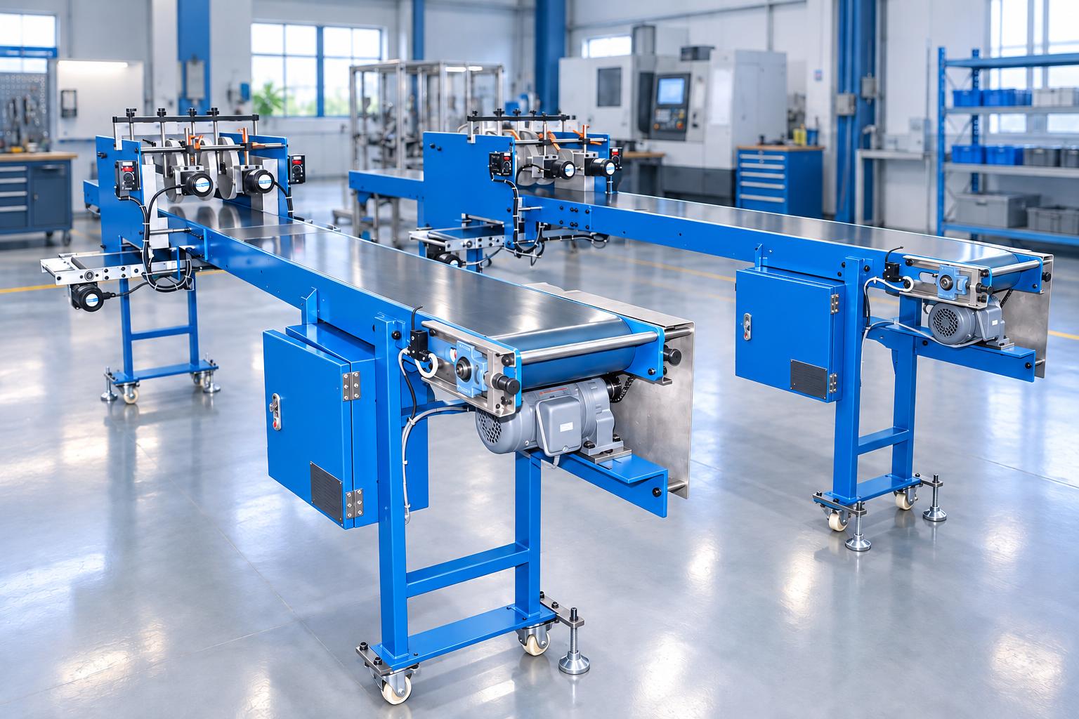
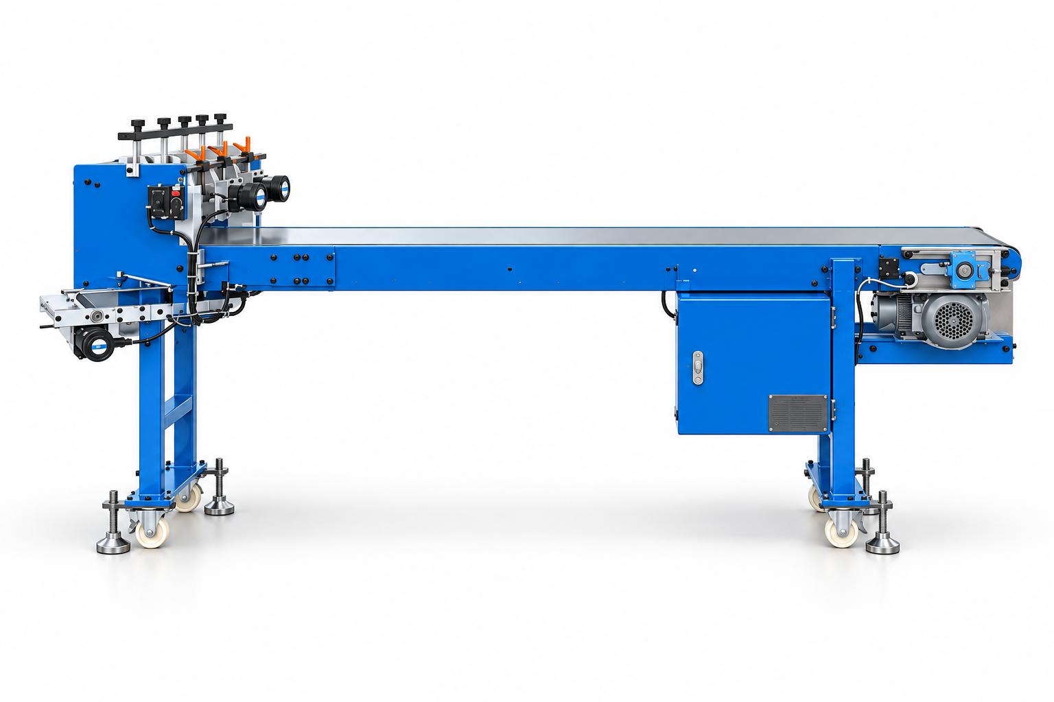
Conveyor system integrated with cutting blades and chip-removal brushes
CNC VINA's conveyor system integrated with cutting blades and chip-removal brushes combines product transportation with processing mechanisms arranged within a single system. The reference configuration includes a main PVC belt conveyor, a set of four disc-shaped cutting blades, two chip-removal brushes, and a lower conveyor belt.
The spacing and height of the cutting blades, as well as the brush contact positions, can be mechanically adjusted to suit the product. Operators control the machine using start and stop buttons and speed controllers. Processing quality should be evaluated based on product stability on the conveyor, cutting tool configuration, and operating speed.
CNC VINA can design the system according to transportation requirements, cutting processes, and factory layout conditions. The design is developed based on product samples, post-processing requirements, and the connection with upstream and downstream production stages.
VIETNAM CNC & TECHNOLOGY APPLICATION JOINT STOCK COMPANY
Hotline: +84.916 63 9355 / +84.915 74 4664
Email: Sales01@cncvina.com.vn / Sales03@cncvina.com.vn
Product description

CNC VINA conveyor system integrated with cutting blades and chip-cleaning brushes combines product transportation with processing mechanisms installed on a single system. A typical configuration includes a main PVC belt conveyor, a set of four disc-shaped cutting blades, two chip-cleaning brushes, and a lower conveyor belt. The blade spacing and height, as well as the brush contact positions, are mechanically adjusted to suit the product. Operators control the machine using start and stop buttons and a speed controller. Processing quality should be evaluated alongside product stability on the conveyor, blade configuration, and operating speed. CNC VINA can design customized systems based on transportation requirements, cutting operations, and available factory space. The proposed solution is developed according to product samples, post-processing requirements, and the connection method with upstream and downstream processes. So, what role does a conveyor system integrated with cutting blades and chip-cleaning brushes play in optimizing production processes? In the following article, let's explore the details with CNC VINA!
Role in the production process
When products need to pass through the cutting and chip-cleaning zones, the conveyor path must be suitable for product placement, processing positions, and surface finish requirements. Integrating the conveyor with these mechanisms helps organize the production process along a defined transport direction with predetermined working positions.
The main conveyor moves products through the processing zone. The blades are positioned at the required spacing and height, while the brushes are adjusted to contact the areas where chip removal is needed. The machine frame, drive system, and control system work together to coordinate the operation of the machine's components.
The key factors to evaluate are whether products move steadily through the cutting zone, whether the processing results meet the required specifications, and whether chips are removed according to the designed configuration.
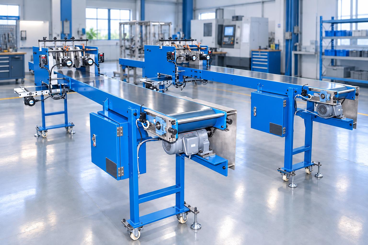
Key features of the conveyor system integrated with cutting blades and chip-cleaning brushes
The system combines a PVC belt conveyor with a cutting blade assembly, chip-cleaning brushes, and a lower conveyor belt.
- The reference configuration includes four disc-shaped cutting blades and two chip-cleaning brushes.
- The spacing between blades and blade height can be mechanically adjusted.
- Brush position and height can be adjusted according to the product contact area.
- The main conveyor is driven by a geared motor and inverter, while the brush motors are equipped with speed controllers.
- The system includes start, stop, and emergency stop buttons, indicator lights, and a switch that triggers the main conveyor to stop.
- The frame is equipped with locking casters and adjustable feet for height and leveling.
Structure and technology
Main PVC belt conveyor
The PVC belt runs over a drive roller, an idler roller, and a supporting surface to transport products. The reference configuration features a main belt approximately 300 mm wide. The actual support area must suit the shape, dimensions, and placement of products as they pass through the cutting assembly.
Belt tension and surface condition affect conveyor movement. During installation or product changeover, the belt tracking, stability under product load, and connection points with related production stages should be checked.
Mechanically adjustable cutting blade assembly
The blade assembly positions disc-shaped cutting blades in the working area above the conveyor. The spacing between blades is adjusted by moving the assembly and locking it in position. Blade height is set using bolts and nuts according to product requirements.
The blade configuration must suit the material, cutting locations, and desired results. During design, the blade type, mounting method, working area, and scope of blade supply should be clearly specified to ensure compatibility between the tooling and conveyor system.
Motorized chip-cleaning brushes
Two brushes are installed in the processing area, each driven by a motor with a speed controller. Brush position, spacing, and height are mechanically adjusted. Brush contact must suit the areas requiring chip removal while protecting the product surface.
Cleaning performance is evaluated based on the amount of residual chips, surface condition, and chip discharge path after brushing. If the process requires dedicated chip collection or dust control, these requirements must be defined during the overall system design.
Lower conveyor belt
A separate belt conveyor with its own motor is installed beneath the processing area. This unit provides an additional transport path within the system. When selecting the configuration, the material to be transported on the lower belt, the receiving position, and the discharge point must be identified to ensure compatibility with the product and chip flow of the process.
Drive system and speed control
The geared motor, chain drive, and drive roller work together to move the belt. An inverter controls the main conveyor motor, while speed controllers regulate the brush motors according to the system configuration.
The conveying speed must be selected in coordination with brush operating speed and cutting requirements. During machine testing, the processing results should be evaluated using actual products at the intended operating rate rather than testing each unit separately.
Push-button and relay control system
The system uses start, stop, and emergency stop buttons, indicator lights, and a relay circuit. Operators start and stop the conveyor and adjust the speed controllers according to the operating instructions. A switch is installed to trigger the main conveyor to stop; its position and function must be verified during system commissioning and handover.
Frame and protective covers
The frame features adjustable feet for height and leveling, along with locking casters to facilitate machine positioning. Protective covers are installed according to the design. The installation area must provide sufficient space for product loading and unloading, as well as access to the cutting blades, brushes, and belt for adjustment and maintenance.
Operating procedure and maintenance of the chip-cleaning brush conveyor
The conveyor system integrated with cutting blades and chip-cleaning brushes must be operated according to the machine configuration and actual processing requirements. Pre-operation inspections, monitoring during operation, and periodic maintenance help maintain conveying performance, chip-cleaning effectiveness, and overall system stability.
The following outlines the operating steps and maintenance considerations necessary to ensure safe equipment operation and compatibility with the production line.
Operating steps for the conveyor integrated with cutting blades
Before starting the machine, the operator checks the blade and brush positions, belt condition, and protective covers. All adjusted components must be securely locked in place. The power supply and connections to upstream and downstream processes must be verified according to the machine configuration.
A typical operating sequence includes:
Step 1: Adjust the blades and brushes to suit the product specifications while the machine is stopped and the power source has been isolated in accordance with the operating instructions.
Step 2: Switch on the power supply, check the system's ready status, and start the machine using the start button.
Step 3: Load products onto the conveyor according to the agreed feeding method. The conveyor transports them through the cutting and brushing zones.
Step 4: The processing units perform their functions according to the configured positions and speeds. The lower conveyor operates in accordance with the designed material flow.
Step 5: Receive and inspect the processed products. Press the stop button when the operation is complete, or use the emergency stop in the event of an emergency.
When changing product specifications, the blade and brush positions must be rechecked, and the first processed product must be inspected. The product loading and unloading methods, as well as the machine's integration with the production line, must be designed to suit the desired level of automation.
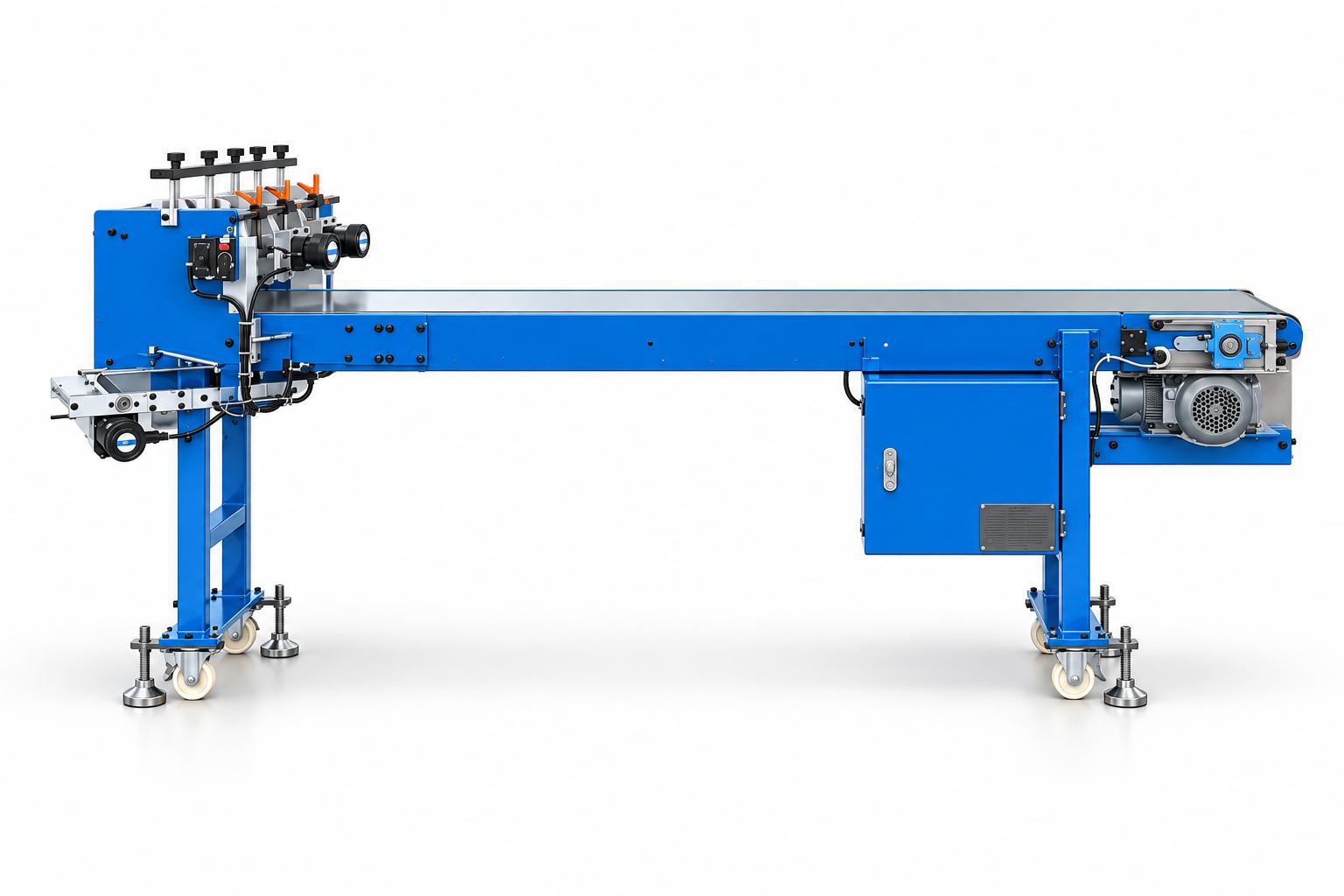
Operating and maintenance considerations for the conveyor with cutting blade assembly
Before each shift, check the positions of the blades and brushes, locking connections, belt condition, and moving areas. If belt misalignment, unusual noise, or changes in processing results occur, identify the cause before resuming production.
Maintenance items include the main and lower conveyor belts, chains, rollers, bearings, motors, bolts, blades, brushes, push buttons, switches, and electrical cabinet. Monitoring belt tension, belt surface condition, mechanical movement, and stop signals helps maintain proper operating conditions.
Before making adjustments, cleaning, or replacing components in moving areas, stop the machine and isolate the power supply in accordance with the instructions. Blades and brushes must be handled by trained personnel using methods appropriate to the delivered machine configuration.
Applications in industrial manufacturing
The conveyor system can be flexibly designed to integrate cutting, chip cleaning, and product transportation within a single production line. Depending on product characteristics, processing requirements, and available floor space, the layout is selected to ensure stable product movement, meet processing requirements, and suit the manufacturer's production workflow.
- Product transportation through cutting operations: The system can be designed for processes that require products to pass through predetermined cutting positions along the conveyor line. Manufacturers need to identify the material, cutting areas, and post-cutting requirements to select suitable blades and product support and guiding methods. The system's suitability for each product type must be verified through actual product testing.
- Combining blade processing with chip cleaning: When a process requires chip removal in the machining area, brushes can be positioned and adjusted according to the required contact area. Evaluation should consider processing results, the amount of residual chips, and the effects of brushing on the product surface. The chip collection method is selected according to the process's cleanliness requirements.
- Integrating processing operations into the production line: The conveyor can connect the product loading point to the cutting and brushing zones and the downstream receiving process. Conveyor length, elevation, and discharge arrangement are selected according to the factory layout. For applications involving multiple product specifications, the required range of mechanical adjustments and the inspection procedure after product changeover must be defined.
Technical specifications of the conveyor integrated with cutting blades
The following specifications describe a reference system configuration. Dimensions and processing arrangements for each project must be confirmed based on product samples and the agreed design.
| Item | Reference specifications |
|---|---|
| Machine dimensions | L4000 x W1050 x H1300 mm |
| Main power supply | 3 phase, AC 200V - 50Hz |
| Belt material | PVC |
| Main belt width | 300 mm |
| Number of cutting blades | 4 disc-shaped blades |
| Chip-cleaning brushes | 2 motorized brushes |
| Blade adjustment | Mechanical adjustment of blade spacing and height |
| Brush adjustment | Mechanical adjustment of brush position and height |
| Speed control | Inverter for the main conveyor; speed controllers for brush motors |
| Operating controls | Start, stop, and emergency stop buttons, indicator lights, and relay control |
| Additional unit | Lower conveyor belt with a separate motor |
| Frame configuration | Adjustable leveling feet and locking casters |
The overall dimensions are used to plan the system's installation within the factory. The product range must be defined according to the support surface, blade spacing and height, brush contact area, and processing requirements. Connection heights to upstream and downstream processes must be checked separately during design.
Factors to determine when selecting the system
Product characteristics and processing requirements
The required information includes material, shape, dimensions, weight, placement on the conveyor, and areas to be processed by the blades. The required dimensions after processing, cutting specifications, and acceptable surface condition must also be agreed upon.
Test samples should represent the product specifications intended for production. If products tend to slip, shift, or deform during transportation, the support and guiding arrangements must be evaluated together with the processing mechanisms.
Blade and brush configuration
The number of processing positions, blade spacing, working height, and contact method must be determined. Blades should be selected together with the mounting, replacement, and maintenance arrangements.
For the brushes, the areas requiring cleaning, acceptable residual chip levels, and surface finish requirements should be clearly defined. Any increase in speed or brush contact pressure must be tested on actual products to determine suitable operating settings.
Material flow and production line integration
The product loading and unloading methods, chip discharge path, and function of the lower conveyor must be defined. Connection points must be compatible in terms of elevation, conveying direction, and operating cycle. The factory layout must also provide sufficient clearance for adjusting the blade assembly, replacing brushes, and maintaining the drive system.
A three-phase, AC 200 V power supply is specified for the reference configuration. If the factory uses a different power supply, the electrical requirements must be determined during project design.
Productivity and product changeover
Productivity should be measured by the number of finished products meeting the required specifications under actual loading and unloading conditions. When conveyor speed changes, the product's passage through the cutting zone, cleaning effectiveness, and downstream receiving capacity must be reevaluated.
Product changeover planning should account for downtime, adjustments, position locking, and inspection of the first processed product. The range of products that can share the same machine depends on their characteristics and the adjustment capabilities of the processing units.
Product testing and evaluation before handover
Testing actual products provides the basis for confirming compatibility between the conveyor, blades, brushes, and operating method. The following items should be checked:
- Products are properly supported and travel in the correct direction through the processing zone without shifting or becoming obstructed beyond the agreed operating limits.
- Cutting position, dimensions, and cut quality meet the specified criteria for each product sample.
- The brushes meet the requirements for residual chip levels and surface condition.
- The lower conveyor transports materials along the intended path and transfers them appropriately according to the designed layout.
- Product feeding, processing, and unloading operate in a stable, coordinated cycle at the intended working speed.
- Results remain consistent with the approved standards after product changeover.
- Control buttons, switches, emergency stop functions, and protective covers are checked according to their designed functions.
Test results should be recorded together with the product sample, blade type, blade and brush positions, speed settings, and product loading and unloading conditions. These records provide a basis for confirming the final configuration and agreeing on the handover acceptance criteria.
Frequently asked questions
What types of products is the machine suitable for?
The processing range is determined by the material, shape, placement on the conveyor, and cutting and brushing requirements. CNC VINA can evaluate product samples to select a suitable solution and verify the results before finalizing the system configuration.
What needs to be done when changing the blade spacing?
Blade spacing and height are mechanically adjusted, and the positions are then securely locked. When changing product specifications, the first processed sample must be inspected, and the relevant brush positions and product guiding arrangements must be checked and confirmed.
What criteria are used to select the operating speed?
The speed must suit product stability, cutting results, chip-cleaning effectiveness, and the product loading and unloading cycle. The operating settings are selected through sample testing and actual performance measurements.
How is chip-cleaning effectiveness evaluated?
The evaluation should include the amount of residual chips in the processing area, the effects of the brushes on the product surface, and the chip discharge path after brushing. Acceptance criteria are agreed upon according to the requirements of the downstream process.
What needs to be determined if the factory uses a different power supply?
The reference configuration uses a three-phase, AC 200 V, 50 Hz power supply. For a different power supply, suitable motor specifications, speed controllers, and electrical cabinet arrangements must be determined during project design.
The conveyor system integrated with cutting blades and chip-cleaning brushes combines product transportation and processing operations within a single system. The equipment can be designed according to product characteristics, cutting requirements, and factory layout conditions. Integrating cutting blades, cleaning brushes, and conveyor belts helps organize product flow through predetermined processing positions in a defined sequence. To ensure stable operation, the appropriate configuration must be selected, and processing quality must be verified using actual product samples. In addition, proper operating procedures and regular maintenance help maintain the equipment's condition. CNC VINA provides conveyor system design and manufacturing services tailored to customers' operational requirements and production conditions. Contact CNC VINA for consultation on a solution suited to your products and actual production line.