 Tiếng
Việt
Tiếng
Việt
 Tiếng
Anh
Tiếng
Anh
 Tiếng
Nhật
Tiếng
Nhật




 Tiếng Anh


Engine air leak tester
Engine air leak tester (air tightness tester) helps check the tightness of car engines with simple operation, intuitive and reliable results.
The engine air leak tester provided by CNC-VINA to customers is the optimal testing solution for automobile and motorbike assembly lines.
Contact us for more advice on testing machines and automation solutions for your products:
VIETNAM CNC & TECHNOLOGY APPLICATION JOINT STOCK COMPANY
Hotline: +84.916 63 9355 / +84.915 74 4664
Email: Sales01@cncvina.com.vn / Sales03@cncvina.com.vn
Product description

Engine air leak testing machine is equipment used to check the airtightness of chambers and internal passages in engines during the manufacturing process. The machine helps detect potential leakage points at an early stage, supporting product quality control before the engine proceeds to subsequent production stages. The testing process combines an air supply system, positioning jig, and water bath to detect air leakage. The machine provides an effective solution for ensuring that finished products meet the required quality standards and preventing leakage in air and fluid passage systems. Measuring instruments imported from Japan and pneumatic components from Germany are integrated into the machine to provide high testing accuracy and stable operation. Therefore, the engine air leak testing machine is widely used in the automotive and motorcycle industries, as well as for testing pneumatic equipment, hydraulic systems, and other industrial components. So, what benefits does an engine air leak testing machine bring to a production line? Let’s explore with CNC VINA in the following article.
Overview of the engine air leak testing machine
The engine air leak testing machine, also known as an engine airtightness testing machine or engine leak testing machine, is designed to check the airtightness of internal chambers and passages in engines before the products move on to subsequent assembly or finishing processes. The machine supplies compressed air to the areas requiring inspection and combines sealing mechanisms with a dedicated product fixture to detect potential leakage.
During the production of automotive and motorcycle engines, many oil chambers, cooling passages, and fluid or air passages must maintain a specified level of airtightness according to the product design. Even a small leak at a mating surface, sealing plug, passage, or connection point can affect the quality and performance of the engine during operation.
Therefore, airtightness testing is an important stage in engine quality inspection. Instead of relying solely on individual manual inspection methods, the engine air leak testing machine helps standardize the testing procedure, improve process control, and enable operators to quickly identify areas showing signs of leakage.
Designed and manufactured by CNC VINA, the engine air leak testing machine can be customized according to the product structure, inspection points, and technological requirements of each production line. The machine can integrate a dedicated inspection jig, air supply system, water tank, conveyor, lifting mechanism, and clamping mechanism to form a complete testing station.
Technical specifications of the engine air leak testing machine
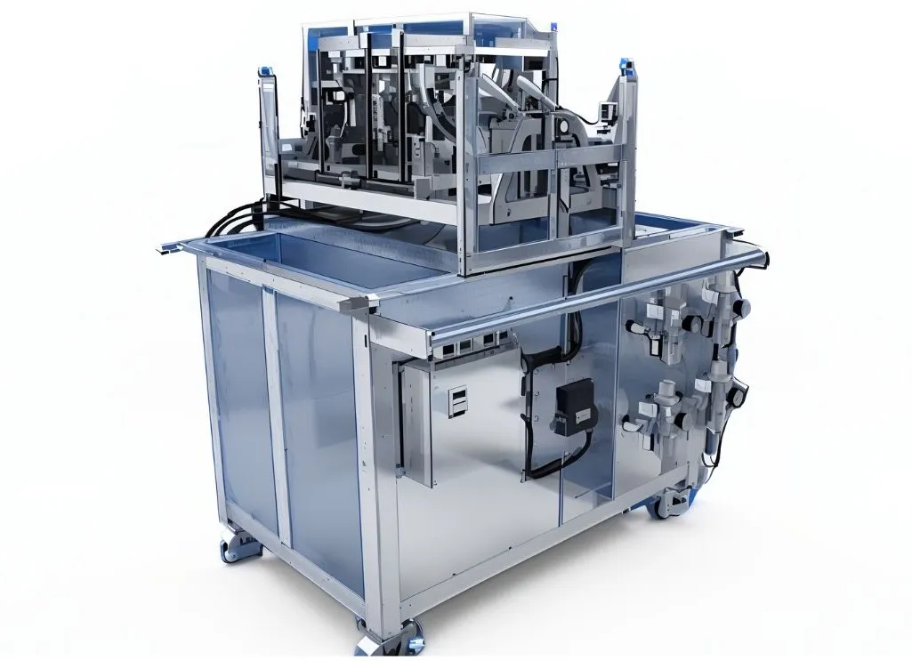
| Machine dimensions | L2870 × W1150 × H1570 mm |
| Water tank dimensions | L1100 × W1700 × H700 mm |
| Air tank capacity | 10 L |
| Air supply pressure | 0.4–0.6 MPa |
| Maximum operating pressure of air tank | 2 MPa |
| Inspection capacity per cycle | 3 positions |
| Number of operators | 1 operator |
| Color | Customizable |
Application of engine air leak tester in the automobile and motorbike assembly industry
n an engine assembly line, the airtightness testing process is typically carried out after the product has completed the machining or assembly steps related to the chambers and passages being inspected. Performing the test at the appropriate stage helps detect defects before the product moves further along the production line. If an air leak is detected early, the engine can be returned to the relevant process for inspection and correction instead of continuing through the assembly line and discovering the problem at a later stage.
The engine air leak testing machine, also known as an engine airtightness testing machine, is an important inspection system in automotive and motorcycle manufacturing and assembly lines. For vehicles powered by internal combustion engines, such as cars and motorcycles, the engine plays a central role in the operation of the vehicle. An internal combustion engine generates power by burning fuel inside the combustion chamber and converting the pressure of the expanding gases into mechanical work. Therefore, maintaining proper airtightness within the engine is an important requirement during manufacturing. A properly sealed engine helps maintain the designed operating performance, improve fuel efficiency, and support safe and reliable vehicle operation. The engine leak testing machine is used to check the airtightness of the engine and identify potential leakage points that may affect product quality.
Closed testing machine for engines along with automatic machines for the automobile and motorbike industry such as static testing machines , fatigue testing machines, steering wheel testing machines, push button testing machines, frame number engraving machines ... help check technical parameters. Strict engineering of product structure, ensuring accuracy and safety during vehicle operation.
CNC VINA provides inspection machines and testing machines for most equipment components, spare parts and accessories for cars and motorbikes according to customer requirements.
Structure of the automotive engine air leak testing machine
The engine air leak testing machine consists of multiple functional units that work together to perform the inspection process. Depending on the actual production requirements, the machine structure can be customized. The main components typically include:
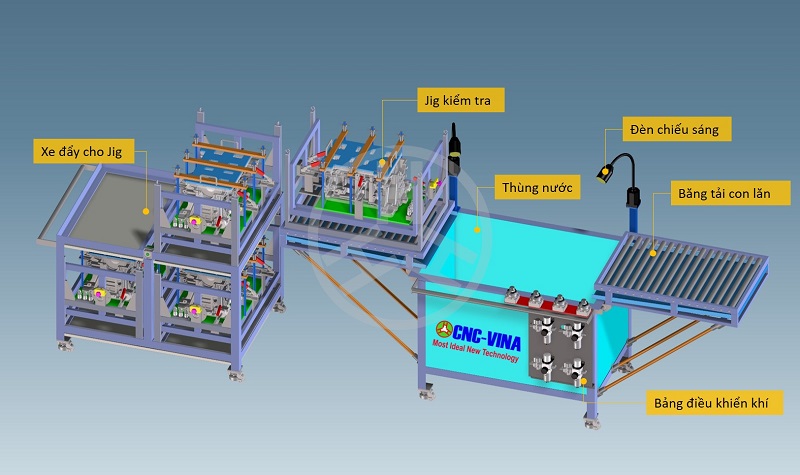
- Jig trolley: The jig trolley is used to store and transport the jigs used during the inspection process. In the current configuration, the trolley has three jig positions and is equipped with wheels for convenient movement within the production area. This arrangement allows operators to prepare products in advance and reduce waiting time between inspection cycles.
- Inspection jig: The jig is the main component used to position and hold the engine during testing. It is designed according to the shape of the engine and the specific inspection points of each product. The jig can be configured for either automatic or manual operation, depending on the requirements of the production line. Since different engine models have different shapes, dimensions, and passage locations, the jig must be designed specifically for each product model to ensure stable positioning and reliable sealing during testing.
- Clamping mechanism: The clamping mechanism holds the product securely and allows the required inspection points to be properly sealed before air is supplied. Depending on the engine design, sealing components may include sealing caps, quick connectors, clamps, or other dedicated components.
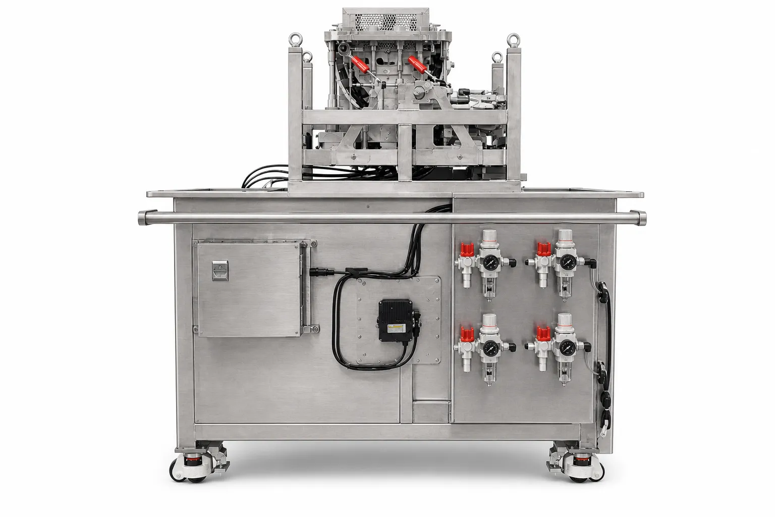
- Water tank: The water tank is the area where air leakage is visually inspected. In the current configuration, the tank is made of stainless steel with a capacity of approximately 0.5 m³. It is equipped with a bottom drain valve and wheels for convenient operation, cleaning, and movement. After the product has been sealed and pressurized, the jig and engine are lowered into the water tank. The operator observes the surface of the engine to detect air bubbles. If the product meets the inspection requirements, no abnormal bubbles should appear at the areas being tested during the specified inspection period. If leakage occurs, air bubbles will appear, helping identify the area that requires further inspection.
- Air supply system: The air supply system delivers compressed air to the inspection points on the engine. The control panel is equipped with quick-connect fittings for convenient connection to different inspection circuits. In the current configuration, the system can be used to inspect areas such as the high-pressure oil chamber, low-pressure oil chamber, and coolant jacket.
- Lighting system: The lighting system provides additional illumination around the inspection area, helping the operator clearly observe the engine surface and detect small air bubbles during the water immersion test.
- Roller conveyor: Roller conveyors are arranged before and after the water tank. The front conveyor is used to hold jigs containing engines waiting for inspection, while the rear conveyor is used to receive jigs containing engines that have completed the inspection process.
- Air supply control panel: The air supply control panel is connected to a compressed air tank with a pressure of up to 20 bar and uses quick-connect fittings for inspecting the high-pressure oil chamber, low-pressure oil chamber, and coolant jacket.
Operating principle and inspection procedure of the engine air leak testing machine
The engine air leak testing machine operates by supplying compressed air to the chambers or passages that need to be inspected and then observing the airtightness of the product in a water environment. The engine is securely positioned on a dedicated inspection jig, while the areas that are not included in the inspection are sealed before compressed air is supplied.
Once the product is immersed in the water tank, any gap or unsealed area will allow the compressed air inside the engine to escape, forming visible air bubbles in the water. Based on the location and appearance of these bubbles, the operator can identify potential leakage points and evaluate the product according to the established inspection criteria.
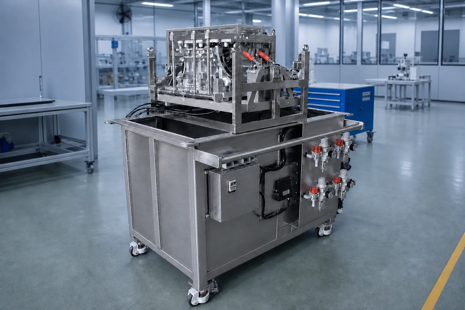
Operating principle of the engine air leak testing machine
The machine operates by supplying compressed air into the chamber or passage to be inspected and observing whether air escapes from any potential leakage point.
First, the engine is placed on the inspection jig and securely positioned at the designated locating points. Ports or passages that are not included in the inspection are sealed. The air supply system is then connected to the chambers requiring inspection. Once the specified test pressure is reached, compressed air is introduced into the chamber. The product is then lowered into the water. If there is a gap or insufficient sealing at the engine housing, mating surfaces, or connection points, the compressed air inside will escape and form visible bubbles on or around the leakage point. The operator evaluates the airtightness of the product based on the location, quantity, and occurrence of air bubbles.
The basic inspection process can be summarized as follows:
Positioning → Clamping → Sealing → Air connection → Air supply → Water immersion → Observation → Result evaluation → Product removal.
Engine air leak testing procedure
The inspection process consists of a series of steps, starting with placing the product on the jig, sealing the required inspection points, supplying compressed air, and performing the water immersion test before evaluating the results. Depending on the level of automation, these operations can be performed automatically by the machine or manually by the operator. Standardizing the inspection sequence helps minimize operating errors and ensures that all products are tested using the same procedure.
Airtightness testing in automatic mode
Step 1: Place the engine on the jig using an external assistive lifting device (automatic jig).
Step 2: Place the upper sealing cover onto the product (automatic jig).
Step 3: Connect the required air lines and supply compressed air (automatic jig).
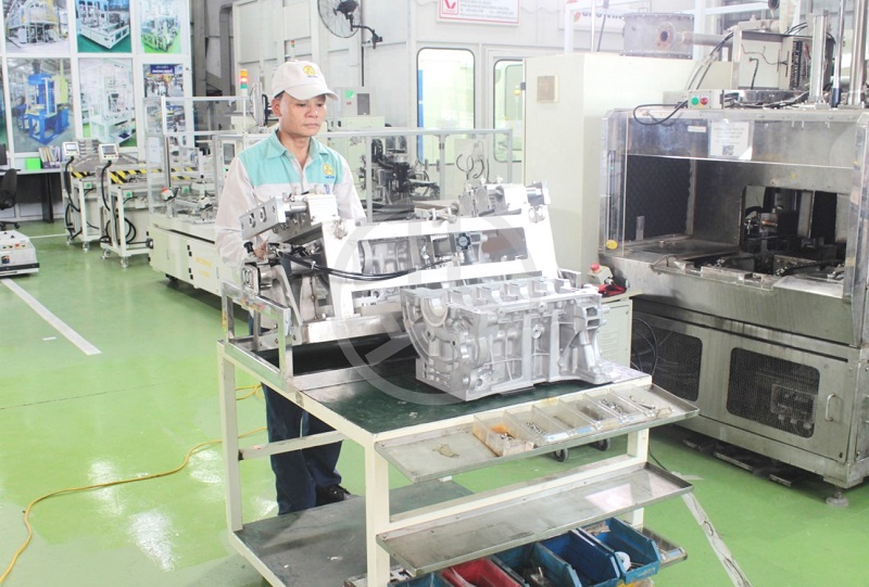
Jig inspection process rotates the product before assembly with an air leak tester
Manual operating mode
Step 1: Place the engine onto the manual inspection jig.
Step 2: Place the upper sealing cover onto the engine.
Step 3: Clamp the sealing points and connect the air supply lines.
Step 4: Lower the jig and engine into the water tank.
Step 5: Rotate the jig manually and observe whether any air bubbles appear.
Step 6: Lift the jig and transfer the inspected engine onto the conveyor behind the water tank, then apply the process label. The next engine is then loaded onto the jig and placed into the inspection area, while a new product is supplied from the jig trolley to the staging table.
The engine air leak testing machine is an important part of the engine quality control process, especially for products that require high airtightness in oil chambers, cooling passages, and internal fluid or air passages. The use of a dedicated inspection jig combined with an air supply system and water tank helps organize the testing process in a clear and consistent manner, making operation easier and allowing potential leakage points to be identified conveniently. The machine can also be customized according to the level of automation required by the production line, from manual operation to integration with lifting mechanisms, conveyors, and other automated equipment. With experience in designing and manufacturing automation machines, testing equipment, and machinery for the automotive and motorcycle industry, CNC VINA can provide consultation and develop suitable engine air leak testing solutions based on each engine model, production volume, and specific inspection requirements of the customer.
Customers who are interested and need to design and manufacture testing machines to serve the automobile and motorbike industries and assembly and inspection lines, please contact CNC-VINA for support:
VIETNAM CNC & TECHNOLOGY APPLICATION JOINT STOCK COMPANY
Factory: Song Cung Industrial Site, Dong Thap Commune, Dan Phuong District, City. Hanoi Vietnam
Phone: +84.916 63 9355 / +84.915 74 4664
Website: https://cncvina.com.vn; https://cncvina.net; https://cncviname.com.vn
Email: Sales01@cncvina.com.vn | Sales03@cncvina.com.vn