 Tiếng
Việt
Tiếng
Việt
 Tiếng
Anh
Tiếng
Anh
 Tiếng
Nhật
Tiếng
Nhật




 Tiếng Anh

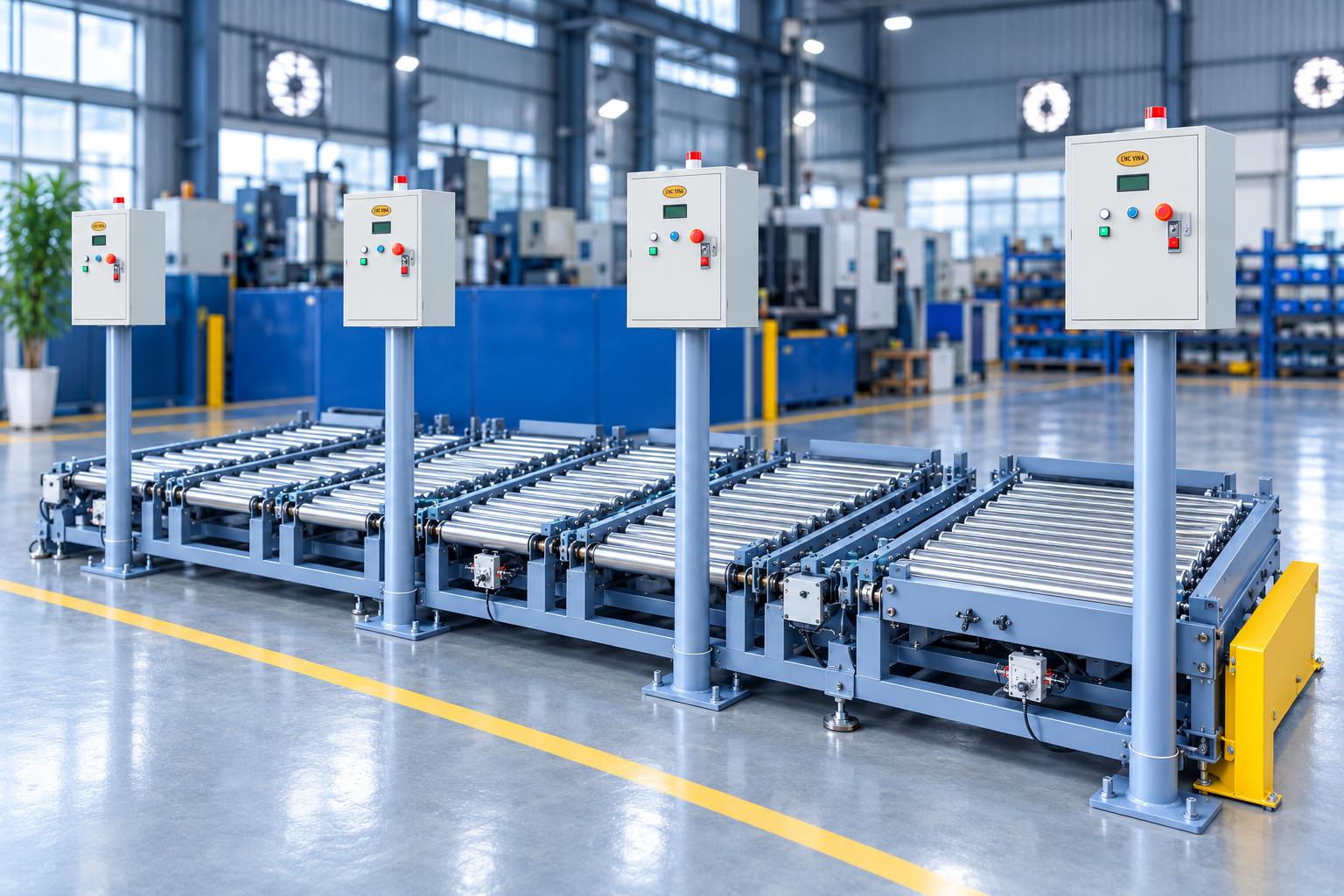
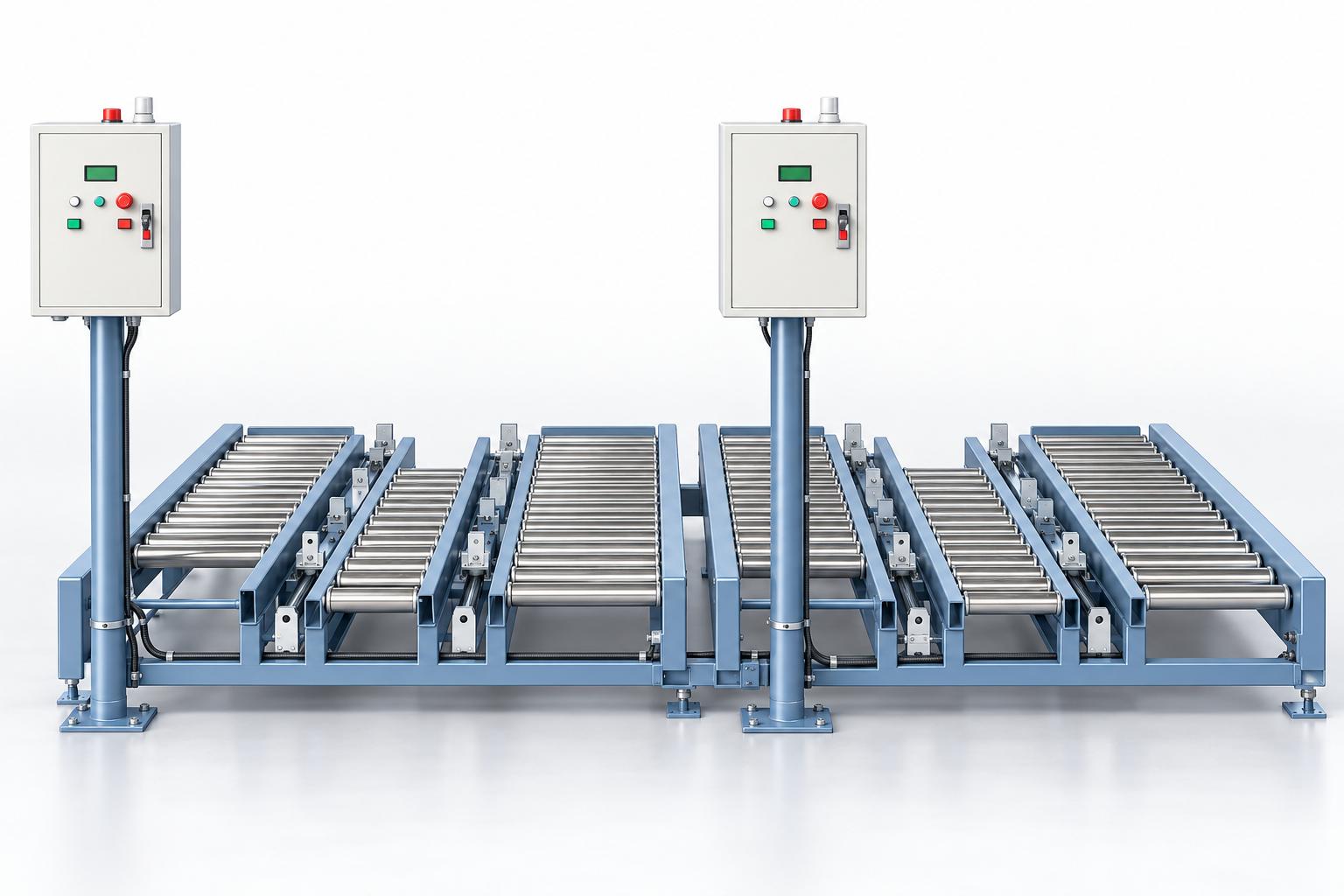
Automatic pallet pushing conveyor
Automatic pallet pushing conveyor, also known as a pallet push system, transfers loaded pallets from a roller conveyor to a transport vehicle waiting to collect them. The pneumatic mechanism uses push lugs and guide components to move pallets one at a time. Before each cycle, the system checks signals confirming pallet presence, vehicle readiness, and control commands. In the reference configuration, the vehicle signals its arrival at the pickup position to the coordinating computer. The computer then issues the push command. Once the transfer is complete, the system sends a completion signal, allowing the computer to instruct the vehicle to continue its route. This coordinated sequence ensures that the machine and vehicle complete the handover in the correct order. CNC VINA can design the pushing mechanism, pallet alignment system, and signal coordination method to suit the pallet type, receiving vehicle, and layout of each factory.
VIETNAM CNC & TECHNOLOGY APPLICATION JOINT STOCK COMPANY
Hotline: +84.916 63 9355 / +84.915 74 4664
Email: Sales01@cncvina.com.vn / Sales03@cncvina.com.vn
Product description

Automatic pallet pushing conveyor, also known as a pallet push system, transfers loaded pallets from a roller conveyor to a transport vehicle waiting to collect them. The pneumatic mechanism uses push lugs and guide components to move pallets one at a time. Before each cycle, the system checks signals confirming pallet presence, vehicle readiness, and control commands. In the reference configuration, the vehicle signals its arrival at the pickup position to the coordinating computer. The computer then issues the push command. Once the transfer is complete, the system sends a completion signal, allowing the computer to instruct the vehicle to continue its route. This coordinated sequence ensures that the machine and vehicle complete the handover in the correct order. CNC VINA can design the pushing mechanism, pallet alignment system, and signal coordination method to suit the pallet type, receiving vehicle, and layout of each factory.
The role of an automatic pallet pushing conveyor in internal material handling
A pallet handover station must ensure that the pallet is in the designated waiting position, the vehicle has arrived at the correct pickup point, and the transfer mechanism has completed its operation before the vehicle departs. The arrangement of these steps directly affects material flow between the production area and the receiving point. The pallet pushing conveyor provides a fixed handover point. The rollers support the pallet, the pushing mechanism transfers it, and the sensors and controller coordinate the operating conditions. When connected to a coordinating computer, pallet transfers are executed according to control commands, with a completion signal confirming that each operation has finished. Performance should be assessed across the entire cycle: pallet preparation, vehicle arrival, condition verification, pallet transfer, and vehicle departure. This provides a basis for selecting the appropriate configuration and determining which tasks still require operator involvement at the pallet loading station.
Key features
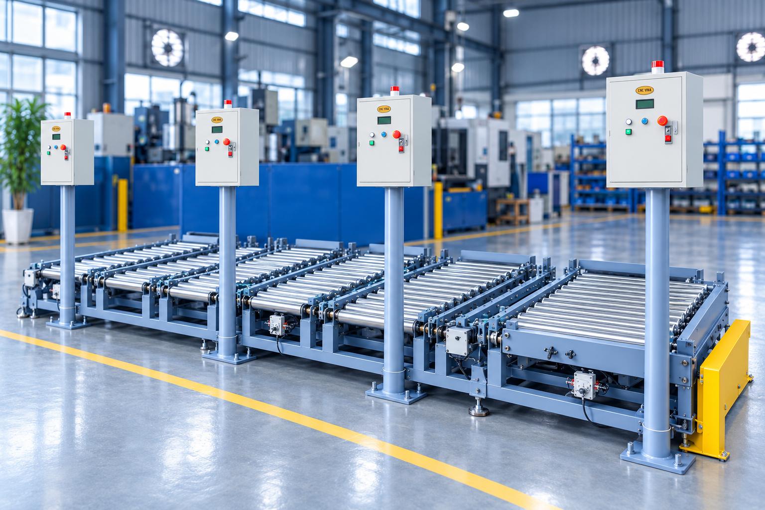
- Transfers pallets from a roller conveyor to a receiving vehicle using a pneumatic pushing mechanism.
- Verifies pallet presence, vehicle readiness, and mechanism status before transferring the load.
- Coordinates push commands and completion signals with a central control computer.
- The reference configuration performs four pushing strokes during one handover cycle.
- Equipped with push buttons, indicator lights, a buzzer, and an LCD for operating status display.
- Can be customized to suit the pallet type, handover point, and transport equipment specified for each project.
Construction and technologies
Roller conveyor and support frame
The roller conveyor provides a supporting surface along which the pallet moves when actuated by the pushing mechanism. This configuration uses non-powered rollers. The pallet base structure, support-bar positions, and flatness must be compatible with the roller layout to prevent interference during transfer. The frame is equipped with adjustable feet and floor-mounting points. During installation, the conveyor handover height relative to the vehicle, floor levelness, and clearance for accessing machine assemblies must be checked.
Cylinders and pallet push lugs
Pneumatic cylinders generate the linear motion of the pushing assembly. The push lugs contact the pallet structure to transmit force, while guide shafts and sliding bushings guide the movement. The springs fitted to the push lugs should also be inspected during maintenance. The reference cycle consists of four successive pushing strokes, with the mechanism retracting between strokes to transfer the pallet onto the vehicle. This stroke count applies to the documented configuration. For other projects, the stroke length and operating sequence must be determined according to the handover distance and the points where the push lugs contact the pallet.
Pallet positioning assembly
The positioning assembly holds the pallet at the working position before handover. The system checks the status of the pallet positioning mechanism and pushing assembly before allowing the sequence to proceed. When changing pallet types, the loading position must be readjusted, and the contact area between the push lugs and the pallet base must be checked.
Vehicle guides at the pickup station
The guide assembly and stopping mechanism help position the receiving vehicle correctly at the pickup station. The vehicle stopping point, clearance between the two supporting surfaces, and handover height must be checked together. When adapting the system for a different vehicle, the mechanical interface and signal coordination method must be reassessed.
Sensors for handover condition verification
Sensors detect pallet presence, vehicle position, and cylinder travel positions. The controller uses these signals to coordinate the positioning and pushing mechanisms. If any required condition is not confirmed, the relevant signals and mechanism status must be checked before operation continues.
Electronic control and LCD display
The reference configuration uses an electronic control board, push buttons, and an LCD. The display shows operating status and pallet and vehicle signals, while indicator lights and a buzzer help operators identify the machine's current condition. Push-button functions operate according to the conditions and instructions specified in the delivered configuration.
Communication with the coordinating computer
The system is equipped with a wireless communication module and a program for exchanging commands with the coordinating computer. During automatic operation, the computer receives the vehicle arrival notification, issues the push command, and receives the completion signal before authorizing the vehicle to proceed. When integrating the conveyor with other systems, the signal definitions, transfer-permission conditions, and procedures for handling communication interruptions must be agreed upon in advance.
Pneumatic system
Compressed air passes through a filter, pressure regulator, and control valves before being supplied to the cylinders. Air pressure, flow rate, and supply stability affect the movement of the pushing mechanism. When selecting the configuration, the actual pallet transfer requirements must be assessed together with the stroke length, contact positions, and roller condition.
Operating principle of the automatic pallet pushing conveyor
The handover cycle of the reference configuration consists of the following steps:

- A pallet is positioned at the machine's waiting station, and the transport vehicle arrives at the pickup point.
- The vehicle sends an arrival notification to the coordinating computer, which then issues a push command to the system.
- The controller checks the signals confirming pallet presence, vehicle readiness, and the positions of the required mechanisms. The pallet positioning mechanism is then released in the specified sequence to initiate the transfer.
- The pushing assembly performs a sequence of extension and retraction strokes, transferring the pallet from the roller conveyor onto the vehicle.
- Once the cycle is complete, the system sends a completion signal to the coordinating computer, allowing the vehicle to leave the handover station.
The method of supplying pallets to the waiting station must be determined during overall system design in coordination with the preceding process. The machine's automation functions focus on verifying operating conditions and pushing the pallet onto the receiving vehicle.
Applications in manufacturing and internal logistics
Pallet handover after the loading or stacking process. Once goods have been arranged on a pallet, the pushing mechanism can transfer it to a transport vehicle at a designated pickup point. This application is suitable for factories that need to coordinate goods dispatch points with internal material flow. The pallet and load arrangement must be compatible with transfer by rollers and push lugs.
Transfer of semi-finished products between production areas. When semi-finished products are placed on pallets, a designated pushing station can be configured to transfer them onto a vehicle for delivery to the next process. Product stability during transfer and pallet compatibility with the receiving vehicle must be verified.
Supplying pallets to transport routes leading to storage or packaging areas. The system can be installed at the handover point between a production area and a transport vehicle carrying goods to the receiving location. Command exchange with the coordinating computer helps synchronize the timing of material transfer. The integration plan must be developed according to the existing workflow and equipment.
Reference technical specifications
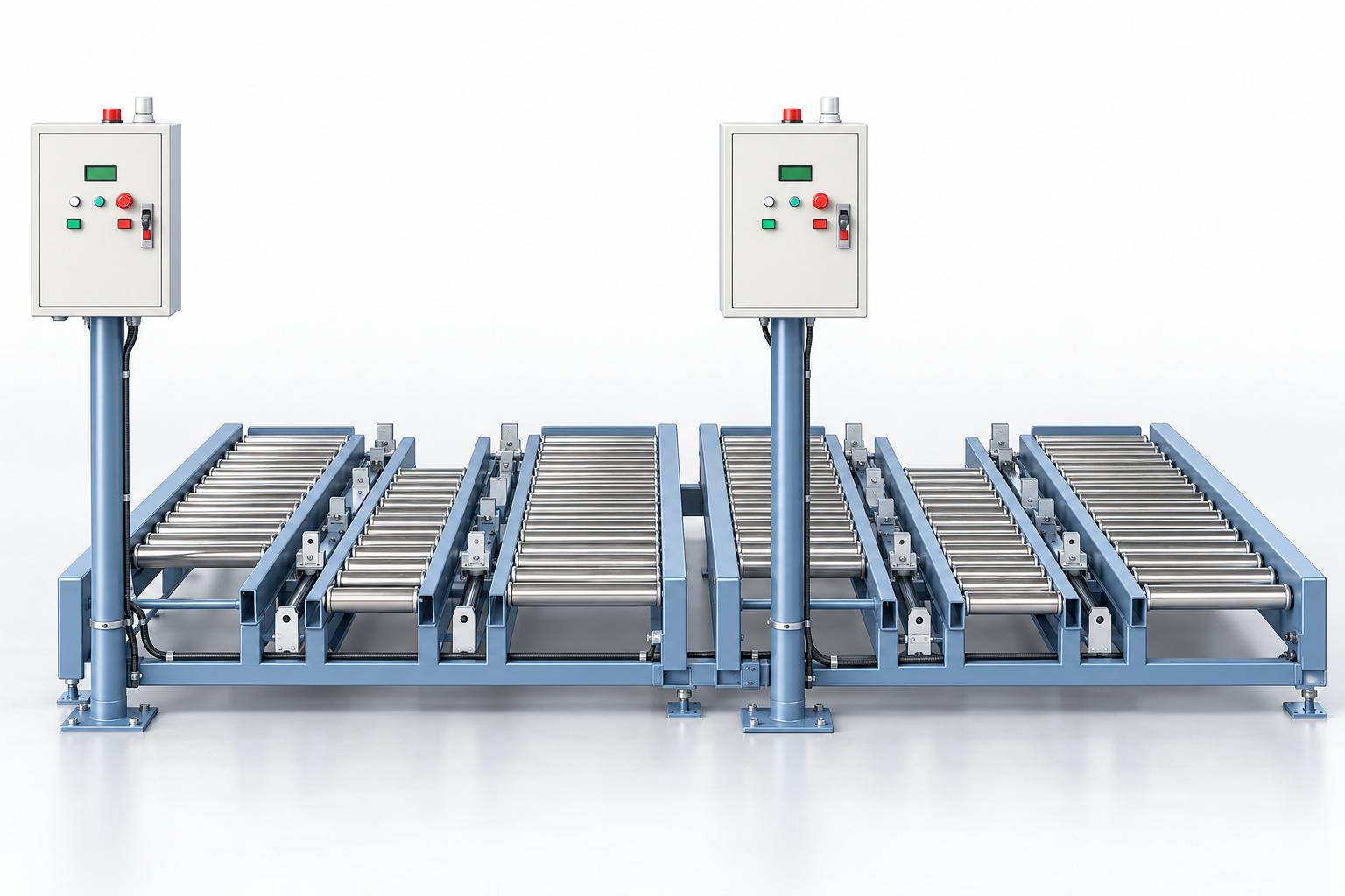
The following table describes the configuration documented in the reference material. Specifications for each project must be confirmed based on the loaded pallet, transport vehicle, and actual equipment layout.
| Item | Reference specifications |
|---|---|
| Overall dimensions (L × W × H) | Approx. 1,700 × 1,700 × 1,500 mm |
| System weight | Approx. 450 kg |
| Pallet load limit specified in the drawing | Under 350 kg |
| Pallet width in the reference configuration | 950–1,280 mm; adjustment required when changing pallet types |
| Main power supply | AC 220 V, single-phase |
| Control voltage | DC 24 V |
| Compressed air supply pressure | 0.4–0.5 MPa |
| Pallet transfer mechanism | Pneumatic cylinders and push lugs |
| Pallet support surface | Non-powered rollers |
| Reference pushing cycle | Four pushing strokes per handover |
| Control and display | Electronic control board, sensors, push buttons, and LCD |
| Automatic coordination | Exchange of commands and completion signals with the coordinating computer |
The system weight of 450 kg must be distinguished from the pallet load limit of under 350 kg specified in the drawing. When finalizing the configuration and conducting machine trials, the method of calculating the combined weight of the pallet and its load, as well as the load distribution conditions, must be agreed upon. The overall height listed in the table must also be distinguished from the roller height at the handover point.
Key factors to determine when selecting the system
Pallet specifications and push-lug contact positions
The buyer should provide the pallet dimensions, bottom structure, combined weight of the loaded pallet, and product stacking arrangement. The push-lug contact areas must be compatible with the pallet structure, and the clearances and support conditions must be checked throughout the entire transfer stroke. Different pallet types may have the same width but differ in length, bottom rails, or structural rigidity. Test samples should represent the pallet types intended for use to verify push-lug contact, transfer stability, and handover to the receiving vehicle.
Receiving vehicle and signal coordination
The vehicle type, stopping position, support-surface height, clearance, and approach direction must be specified. The machine and vehicle must coordinate the ready-to-receive, transfer-permission, and handover-completion signals according to the system design. The integration plan must also define the system response when the vehicle has not arrived, no pallet is present, or a required signal has not been confirmed. These conditions affect operating procedures and cycle recovery.
Installation space and accessibility
The reference documentation specifies an installation area of approximately 1.8 × 1.8 m. The actual layout must also accommodate the vehicle approach path, pallet supply position, and access for inspection and maintenance. The handover height must be confirmed in conjunction with the receiving vehicle.
Material supply cycle and pallet changeover
Throughput must be calculated based on the time required to complete one pallet handover, including vehicle arrival, signal verification, pushing mechanism operation, and vehicle departure. Four pushing strokes represent the mechanism sequence for one handover, not the number of pallets completed per unit of time. In the reference configuration, operation must be paused and the pallet position readjusted when changing pallet types. Compatibility across different pallet types must be verified based on dimensions, bottom structure, push-lug contact areas, and the handover arrangement with the vehicle.
Testing and evaluation before acceptance
Testing with actual loaded pallets helps evaluate the pushing mechanism, rollers, receiving vehicle, and control system together. The following items should be checked:
- The pallet is positioned correctly, and the push lugs contact the designated areas during each pushing stroke.
- The pallet moves smoothly across the handover gap and onto the vehicle without the bottom catching or the pallet deviating from the required direction.
- The pushing mechanism extends and retracts in the correct sequence, and the required sensors confirm the operating states.
- The completion signal is sent at the correct time before the vehicle departs.
- The system responds as designed when a pallet is missing, the vehicle is not ready, or a required signal is lost.
- The actual cycle time meets the expected material supply rate and supports the intended pallet changeover requirements.
- The control functions, emergency stop, and protective guarding are checked within the scope of the system design.
Test results should be documented together with the pallet type, test load, load arrangement, compressed-air supply conditions, and receiving vehicle configuration. These records provide a basis for agreeing on the operating scope and acceptance criteria.
Frequently asked questions about automatic pallet pushing conveyors
In which direction does the pallet pushing machine transfer pallets?
The machine transfers pallets from a roller conveyor onto a transport vehicle waiting to collect them. The mechanical configuration and signal coordination are designed for this specific handover point.
When does the pushing cycle start?
In automatic mode, the system must receive a command from the coordinating computer and verify the required conditions for the pallet, vehicle, and mechanism status. If these conditions are not met, the cause must be checked and addressed according to the system design.
Can the system be integrated with an existing transport vehicle?
CNC VINA can assess an integration solution based on the vehicle currently in use. Before selecting a configuration, the mechanical interface, stopping position, height, pallet receiving method, and communication signals must be verified.
What are the pallet load and dimensional limits?
The reference configuration drawing specifies a pallet load limit of under 350 kg, while the documented pallet width is 950–1,280 mm. The permitted operating range must be confirmed together with pallet length, bottom structure, combined pallet and load weight, load arrangement, and receiving vehicle requirements.
Is adjustment required when changing pallet types?
Yes. The operating instructions require the machine to be stopped and the pallet position readjusted when changing pallet types. For other products, the loading position, push-lug contact areas, and handover conditions with the vehicle must also be checked.
What compressed-air pressure does the machine require?
The reference configuration requires a compressed-air supply pressure of 0.4–0.5 MPa. For each project, the required air flow rate and supply conditions must also be verified to ensure compatibility with the cylinders and operating cycle.
CNC VINA designs automatic pallet pushing conveyors to order
CNC VINA designs and manufactures automatic pallet pushing conveyors according to pallet dimensions, load characteristics, and the receiving equipment used at each factory. The system can integrate a roller conveyor, pneumatic pallet pushing mechanism, vehicle positioning and guiding assemblies, and connections to packaging lines, stretch-wrapping stations, and pallet transfer conveyor systems to optimize internal material flow. Depending on the factory layout and operating requirements, CNC VINA can customize the mechanical structure, control sequence, and handover signals to ensure coordination between processes.
Are you looking for a pallet conveyor system, an automatic roller conveyor, or equipment integration for a packaging line? Contact CNC VINA and provide your pallet dimensions, load weight, upstream equipment details, and handover requirements to receive advice on a suitable solution.
VIETNAM CNC TECHNOLOGY APPLICATION JOINT STOCK COMPANY
Factory: Song Cung Industrial Cluster, Dong Thap Commune, Dan Phuong District, Hanoi, Vietnam.
Office: Rox Tower Goldmark City, 136 Ho Tung Mau Street, Phu Dien Ward, Hanoi, Vietnam.
Tel: +84 916 639 355 / +84 915 744 664.
Website: www.cncvina.com.vn | www.cncvina.net