 Tiếng
Việt
Tiếng
Việt
 Tiếng
Anh
Tiếng
Anh
 Tiếng
Nhật
Tiếng
Nhật




 Tiếng Anh

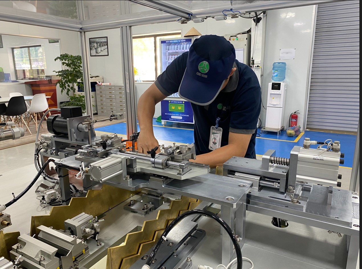
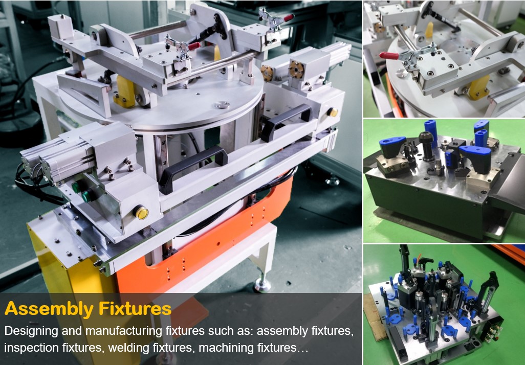
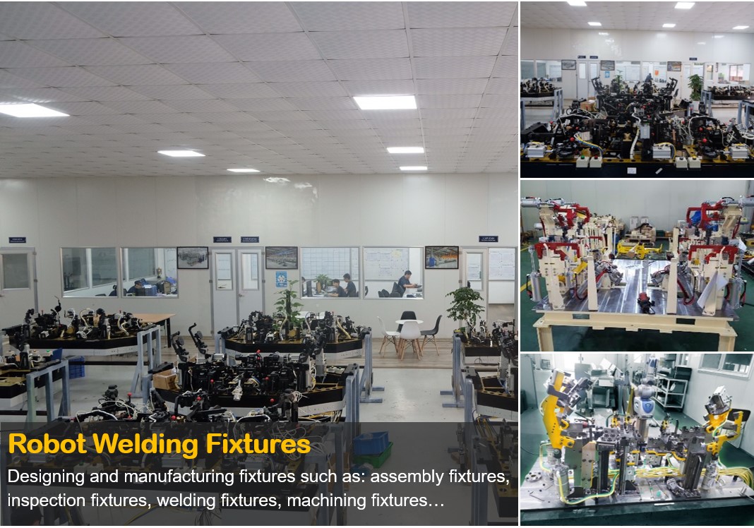
Design and manufacture specialized jigs as required
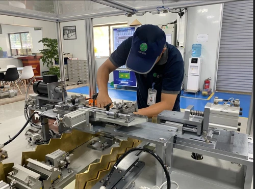
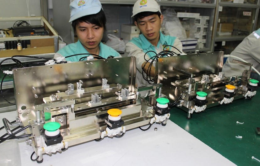
CNC Vina manufactures car seat assembly jigs, automatic clamps, and jigs for on-demand assembly with high accuracy. JIGs, jigs, clamps, and JIGs combined with assembly lines help improve productivity and increase profits.
CNC machining jigs for each type of product and manufacturing process, designed to help change flexibly and quickly according to customer requirements. In the production and assembly line, when combining jigs on automatic conveyors, the jigs are passed through each stage with a certain cycle time to help reduce downtime between stages and improve productivity.
VIETNAM CNC & TECHNOLOGY APPLICATION JOINT STOCK COMPANY
Hotline: +84.916 63 9355 / +84.915 74 4664
Email: Sales01@cncvina.com.vn / Sales03@cncvina.com.vn
Product description

Overview of custom-designed and manufactured fixtures
The design and manufacturing of fixtures, also known as JIGs, is an important process in mechanical manufacturing, particularly in CNC machining, assembly, and automated production lines. Fixtures are used to locate, clamp, and securely hold workpieces during machining or assembly, helping maintain dimensional accuracy and process stability.
Custom-designed and manufactured fixtures are specifically developed based on the workpiece geometry, machining method, accuracy requirements, and actual production conditions. Unlike standard fixtures, which have a broader range of applications, custom fixtures are optimized for a specific workpiece, a group of similar workpieces, or a particular production operation. A properly designed fixture can reduce setup time, improve repeatability, and minimize variation during production. Depending on their intended application, fixtures used in mechanical manufacturing can generally be divided into three main groups: machining fixtures, assembly fixtures, and inspection and measurement fixtures. Each group has different requirements for structure, accuracy, locating methods, and workholding mechanisms, but all are designed to maintain stable workpiece positioning throughout a specific production operation.
Types of custom-designed and manufactured fixtures
Based on their intended application, custom fixtures can be divided into three main groups: machining fixtures, assembly fixtures, and inspection fixtures.
Machining fixtures
Machining fixtures are used to locate and clamp workpieces or blanks on machine tools during machining operations. Depending on the machine type, machining method, and workpiece geometry, the fixture structure can be customized to ensure accurate positioning, secure clamping, and convenient operation for operators or automated systems.
Turning fixtures
On lathes, workpieces can be held using various methods, including chucks, centers, mandrels, collets, or dedicated fixtures designed for specific groups of workpieces. For components machined through rotational motion, the workholding method must ensure secure clamping while maintaining the required concentricity throughout the machining process. For fixtures that rotate together with the workpiece, the structure should be designed to meet the balancing requirements and spindle speed conditions in order to minimize vibration and ensure safe operation.
Dedicated mandrels
Mandrels are commonly used to locate and hold workpieces with internal holes during machining. Depending on the workpiece geometry and technical requirements, mandrels can be designed as plain mandrels, expanding mandrels, spline mandrels, or other dedicated configurations.
Spline mandrels are used for components with internal spline profiles, with the locating and torque-transmitting features designed to match the spline geometry of the workpiece. When designing this type of fixture, factors such as dimensions, tolerances, concentricity, and locating requirements must be carefully considered to ensure stable workholding throughout the machining process. For custom fixtures, components such as centers, mandrels, locating pins, springs, balls, and clamping mechanisms can be combined according to the requirements of each workpiece and machining method. The actual configuration should be determined based on the part drawing, machine tool, locating scheme, and production requirements.
Keyless mandrel: 1.9. Center point, 2. Key mandrel, 3. Ejector spring, 6. Taper pin, 4. Ball (there are three), 5. Details, 7. Pin, 8. Turning wheel.
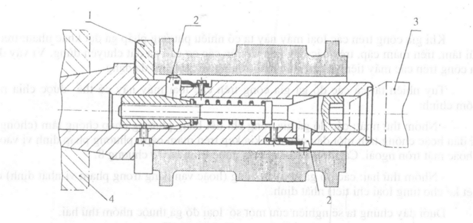
Six-pin mandrel: 1. C-shaped bearing, 2. Pin (there are six, three on each side arranged symmetrically), 3. Center bit, 4. Chuck.
Milling fixtures
In milling operations, fixtures are used to locate and clamp workpieces on the machine table, ensuring that the workpiece remains securely positioned throughout the cutting process. Depending on the workpiece geometry, surfaces to be machined, and required accuracy, the locating scheme can be designed to constrain the appropriate degrees of freedom while also facilitating efficient loading and unloading.
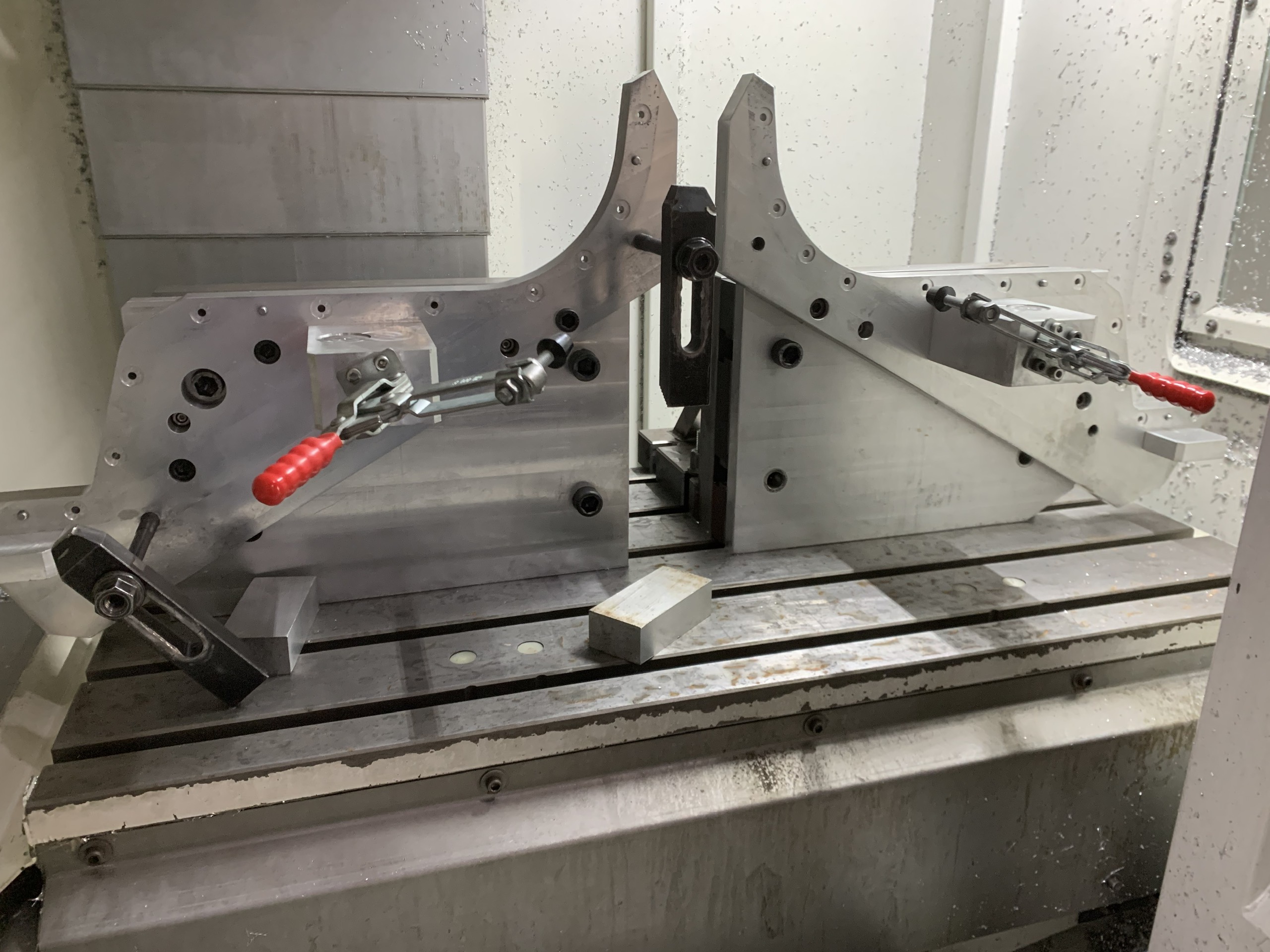
For dedicated milling fixtures, locating and clamping mechanisms are typically designed specifically for the geometry of each workpiece. The positions of support pads, V-blocks, locating pins, and clamping mechanisms must be selected to hold the workpiece securely without causing deformation or interfering with the machining area. The fixture can also incorporate tool-setting stops, guide keys, or other auxiliary mechanisms to reduce setup time and improve repeatability between machining cycles.
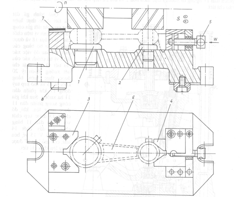
For example, specialized jigs for milling flat surface of fork-shaped parts: 1.2. Spleen plate, 3.4. Block V, 5. Bolt, 6. Fork detail, 7. Tool guide, 8. Then to guide the fixture on the machine table.
Grinding fixtures
Grinding fixtures are used to locate and clamp workpieces during grinding operations, maintaining stable positioning while meeting the required dimensional accuracy, geometric accuracy, and surface finish. In principle, grinding fixtures can adopt some of the locating and clamping approaches used in turning fixtures. However, the fixture structure must be designed according to the specific grinding method, machine type, workpiece geometry, and technical requirements of the surface being machined.
For components requiring high-precision grinding, the fixture must provide stable locating, minimize vibration, and prevent workpiece deformation during machining. Depending on the application, fixtures can be designed to hold the external surface, internal surface, flat surface, or contoured surfaces of the workpiece.
Tapping fixtures
Tapping is an internal thread-forming operation typically performed after a hole has been prepared by drilling, counterboring, or reaming. Therefore, in production, a tapping fixture can be designed based on the locating and clamping scheme used in the preceding hole-making operations, particularly when these operations are performed on the same group of components or within the same production line. However, tapping fixtures must also address the alignment and concentricity between the tapping tool and the pre-machined hole. The fixture must hold the workpiece securely, minimize movement during thread formation, and provide sufficient access for the tapping tool to approach the machining position accurately. For dedicated tapping fixtures, guide bushings, locating pins, quick-clamping mechanisms, or specialized locating mechanisms can be integrated depending on the workpiece geometry and production method. An appropriate fixture design helps reduce setup time, maintain the positional accuracy of threaded holes, and improve process stability in high-volume production.
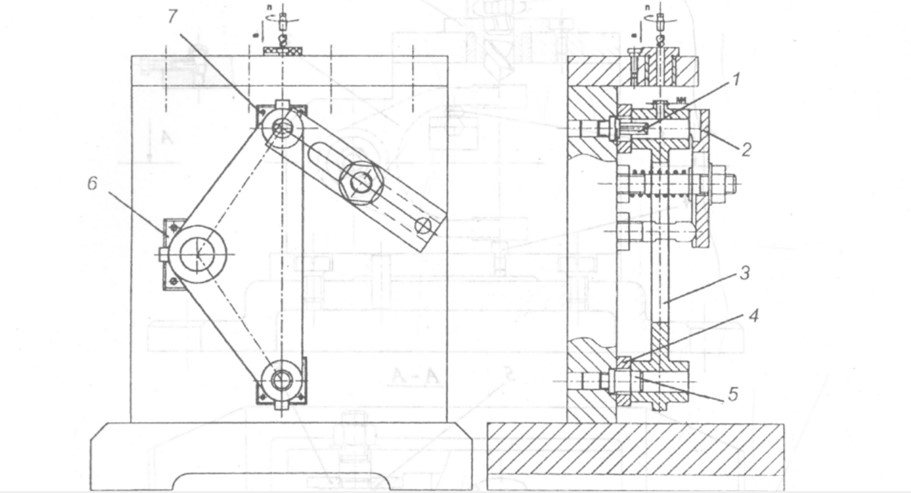
The picture below is a specialized jig for drilling and tapping an M4 hole for a claw-shaped part: 1. Filling pin, 2. Clamp, 3. Machining part, 4.6.7. Spleen plates, 5. Pillar pin.
Welding Fixtures
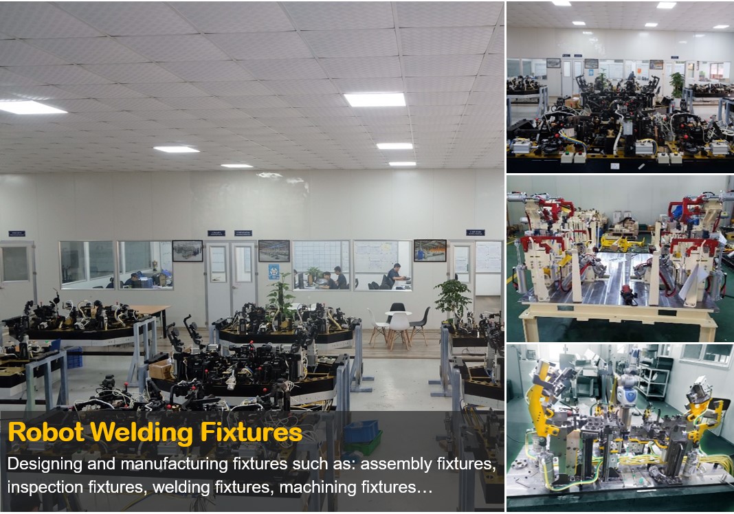
Welding fixtures are used to fix details when making welds, creating conditions for quality welds. Welding fixtures can also be multi-purpose or specifically designed to help speed up the positioning and clamping process, saving welding time.
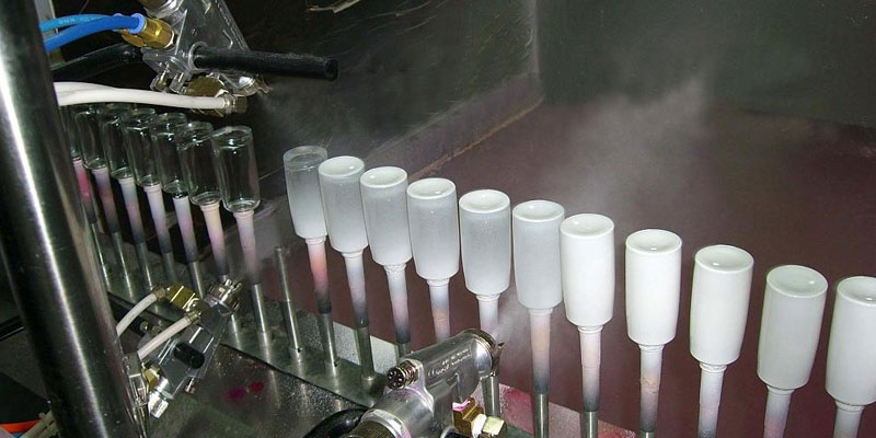
Painting Fixtures
A paint product jig is a type of fixture used to position and clamp the product during the coating process, post-paint drying process, etc. to avoid the product from moving or blowing away due to impact force (Could be from spray gun, dryer steam).
Assembly fixtures
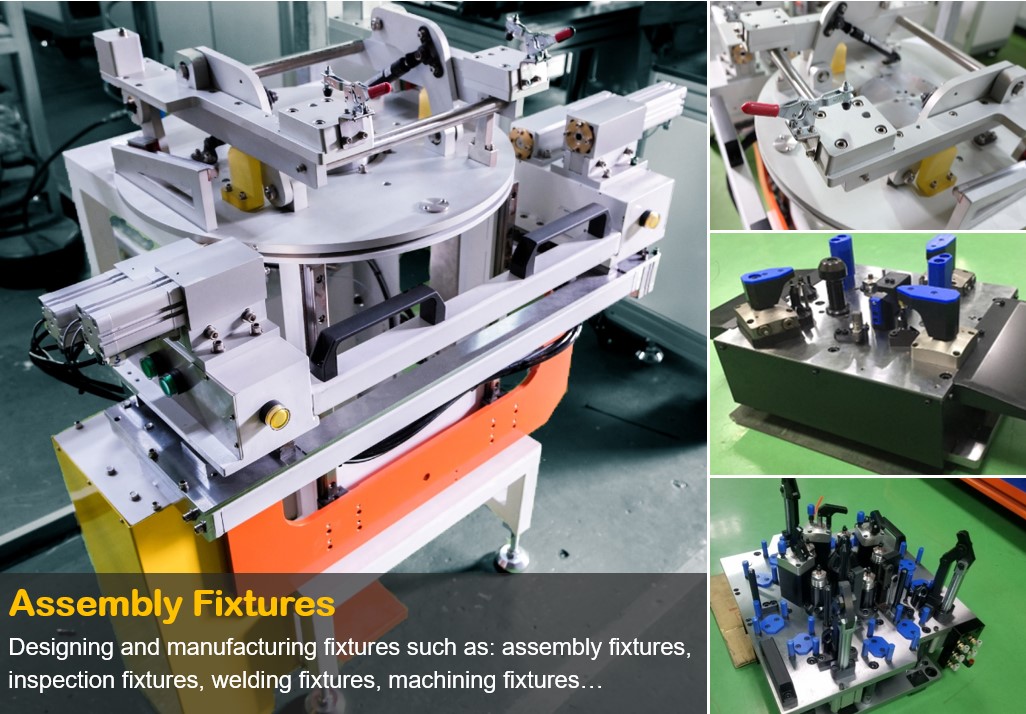
Assembly fixtures are used to locate, hold, and support components or subassemblies in their correct positions during the assembly process. Based on their range of applications, assembly fixtures can be classified into universal assembly fixtures and dedicated assembly fixtures. Universal assembly fixtures have flexible structures and can be adjusted for use with different types of components or products. In contrast, dedicated assembly fixtures are designed according to the geometry, dimensions, assembly positions, and technical requirements of a specific component, subassembly, or product group. This allows dedicated fixtures to provide accurate locating, reduce setup time, and maintain consistent positioning throughout repeated assembly cycles.
Because their structures are optimized for a specific range of products, dedicated assembly fixtures are commonly used for repetitive operations, mass production, or production lines where assembly time and accuracy need to be closely controlled. Although the initial design and manufacturing costs may be higher than those of universal fixtures, their overall efficiency can be improved by reducing setup time, minimizing positional deviations, and increasing productivity when used for an appropriate production volume. When designing dedicated assembly fixtures, factors such as component geometry, assembly positions, locating methods, clamping mechanisms, tool accessibility, and the operating sequence should be considered together. For automated or semi-automated production lines, fixtures can also be integrated with sensors, pneumatic mechanisms, electrical actuators, or other automation equipment to meet the requirements of each assembly operation.
For example, the figure below illustrates a dedicated assembly fixture used to locate and clamp an automotive rear axle differential housing during the assembly process.
Inspection fixtures
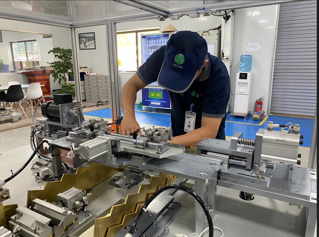
Inspection fixtures are used to locate and hold workpieces in a defined position, facilitating the inspection of dimensions, positional relationships, geometric accuracy, and compliance with the required technical specifications. Depending on the inspection method, fixtures can be used in combination with measuring tools, measuring equipment, or go/no-go inspection mechanisms. Dedicated inspection fixtures are designed according to the geometry, dimensions, inspection datums, and technical characteristics to be evaluated for each type of component or product. Compared with manual fixturing methods, dedicated fixtures help standardize the inspection position, reduce locating time, and minimize operator-induced deviations during measurement and inspection. For products requiring repetitive inspection in high volumes, dedicated inspection fixtures can help shorten inspection time, improve repeatability between measurements, and support consistent quality control throughout the production process. The fixture structure should be designed according to the inspection method, workpiece tolerances, and type of measuring equipment used.
Basic components of an inspection fixture
Depending on the inspection requirements and actual fixture configuration, an inspection fixture may include the following main components:
Locating mechanism: establishes the position of the workpiece according to the selected datums.
Clamping mechanism: holds the workpiece securely during inspection without causing deformation that could affect measurement results.
Inspection or measuring mechanism: supports the inspection of dimensions, positions, or other technical characteristics according to the specified requirements. This component can be integrated directly into the fixture or used in combination with external measuring equipment.
Auxiliary mechanisms: may include guide pins, locking mechanisms, lifting mechanisms, or other components that support operation, depending on the fixture design.
Fixture body or frame: provides the base structure for mounting the locating, clamping, and inspection components.
Basic requirements for dedicated fixture design and manufacturing
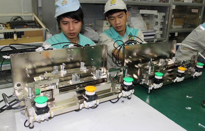
The design and manufacturing of dedicated fixtures and JIGs is an important process in mechanical engineering and machine manufacturing, particularly in CNC machining, mechanical assembly, and the preparation of automated production lines. Depending on their intended application, fixtures can be designed for machining, assembly, or inspection operations. Each type of fixture has different technical requirements based on workpiece geometry, machining methods, required tolerances, equipment used, and actual production conditions.
In general, fixtures are used to locate and maintain workpieces in a stable position during machining, assembly, or inspection. For dedicated fixtures, the structure should be optimized for a specific component or product group to ensure the required accuracy, repeatability, operating time, and stability during use. Several important requirements should be considered when designing and manufacturing fixtures, including:
Accuracy and repeatability
Fixture accuracy should be determined based on the technical requirements of the workpiece and the production operation. Factors such as dimensional accuracy, positional relationships, parallelism, perpendicularity, and concentricity of locating mechanisms can directly affect machining and assembly results. In addition to initial accuracy, the fixture should maintain consistent repeatability over multiple setup cycles. Datum surfaces, locating pins, support pads, and clamping mechanisms must be appropriately arranged so that the workpiece can return to its defined position with deviations within the allowable limits.
Simple and safe setup operations
Dedicated fixtures should facilitate workpiece loading, locating, clamping, and unloading after the operation is completed. In mass production, reducing setup time can help shorten cycle time and improve productivity. Quick-clamping mechanisms, pneumatic mechanisms, or automated support solutions can be incorporated depending on production requirements. At the same time, the fixture should provide adequate working space for operators and minimize the risk of hand injuries, collisions, or contact with moving components.
Rigidity and clamping capability
During machining, assembly, or inspection, the fixture must maintain the workpiece in a stable position under the effects of cutting forces, assembly forces, or other operational loads. The fixture structure should have adequate rigidity to minimize vibration and deformation that could affect machining or inspection results.
Clamping force should also be appropriately calculated and applied. The clamping force must be sufficient to prevent workpiece movement without causing deformation or affecting the surfaces or positions to be machined. The location of the clamping mechanism should be selected based on the workpiece structure, locating scheme, and direction of applied forces during operation.
Durability and wear resistance
Dedicated fixtures may operate at high frequencies and be subjected to repeated loads during workpiece loading, machining, or assembly. Therefore, the fixture materials and structure should be selected according to the expected loads, working environment, and intended number of operating cycles.
Components that are frequently in contact or subject to friction, such as locating pins, support pads, guide bushings, sliding mechanisms, and clamping surfaces, should be evaluated for wear resistance. Depending on the requirements, suitable materials, heat treatment, or replaceable wear components can be used to maintain accuracy and extend fixture service life. In addition, when fixtures are used in environments involving cutting oil, coolant, chemicals, dust, or metal chips, the structure should be designed to minimize the accumulation of contaminants and facilitate cleaning and maintenance.
Stages for dedicated fixture design and manufacturing
The design and manufacturing of dedicated fixtures should be carried out through a clear process to ensure that the fixture meets the required technical specifications, is compatible with the production equipment, and can operate reliably. Depending on the workpiece and intended application, the process can be adjusted accordingly, but it generally includes the following main stages:
1. Collecting requirements and technical specifications
Before starting the design, all requirements from the customer and the actual operating conditions of the fixture should be clearly identified. Important information includes:
-
The workpiece to be machined, assembled, or inspected.
-
Technical drawings and tolerances.
-
The production operation where the fixture will be used.
-
Machine type and installation space.
-
Production volume and frequency of use.
-
Requirements for cycle time, accuracy, and operation.
-
Budget, lead time, maintenance requirements, and expected service life.
Clearly defining the requirements from the beginning helps minimize design changes and maintain better control over manufacturing costs.
2. Analyzing the workpiece and manufacturing process
Based on the drawings and technical data, engineers analyze the workpiece geometry, datum surfaces, tolerances, surfaces to be machined or inspected, and the intended production method.
The following factors should also be considered:
-
The manufacturing process of the workpiece.
-
The fixture setup scheme for each operation.
-
The machine type and installation conditions.
-
The direction of cutting or assembly forces.
-
Accessibility for cutting tools, other tools, and operators.
Based on this analysis, the appropriate locating, clamping, and fixture structure can be determined.
3. Proposing and selecting a design concept
For complex requirements, multiple fixture concepts can be developed and compared in terms of accuracy, rigidity, setup time, manufacturability, level of automation, and cost. After evaluating these factors, the most suitable concept is selected as the basis for detailed fixture design.
4. Fixture design and simulation
Engineers develop a 3D model and design the main mechanisms, including locating mechanisms, clamping mechanisms, guides, the fixture body, and auxiliary components. Depending on the requirements, the design can be evaluated through motion simulation, workspace checks, tool accessibility checks, or force analysis at critical locations. This stage helps identify and adjust potential structural issues before the fixture proceeds to manufacturing.
5. Finalizing drawings and prototype manufacturing
After the model has been reviewed, engineers finalize the manufacturing drawings, tolerances, materials, heat treatment requirements, and other technical specifications for each fixture component. The fixture is then machined, assembled, and inspected according to the design requirements. When necessary, the fixture is trialed on the machine or at the actual production operation to evaluate its locating and clamping performance, repeatability, and operating time before being put into production.
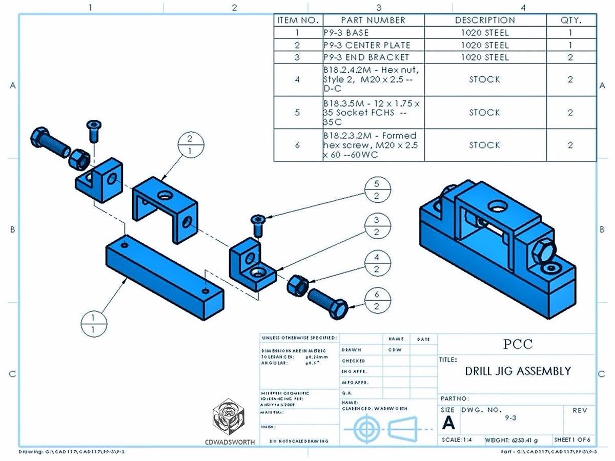
Detailed design process for dedicated fixtures
After the structural concept has been selected, the fixture design needs to be developed into a model and technical drawings containing sufficient information for manufacturing, assembly, and inspection. Key activities at this stage include:
Converting the concept into a model and technical drawings
Initial concepts can be presented as sketches to define the locating and clamping principles and the arrangement of the mechanisms. Once a suitable concept has been selected, engineers use CAD software to develop the 3D model and finalize the technical drawings. The drawings should provide complete information on dimensions, tolerances, materials, machining requirements, assembly positions, and other specifications required to manufacture each fixture component.
Selecting suitable materials
Fixture materials should be selected based on load, clamping force, cutting force, frequency of use, working environment, and durability requirements. Different components may require different materials or treatment methods depending on their functions. For wear-resistant or high-hardness components such as locating pins, bushings, support pads, and certain clamping mechanisms, heat treatment or suitable materials may be required to maintain accuracy throughout the fixture's service life.
Determining dimensions and tolerances
Dimensions shown on technical drawings represent design values and should be assigned tolerances appropriate to the technical requirements and actual manufacturing capabilities. Not all fixture dimensions require the same level of tolerance control; features that directly affect locating accuracy, assembly, or movement should be controlled appropriately. In addition to manufacturing errors, the design should also account for locating errors, datum errors, deformation caused by clamping forces, cutting forces or applied loads, and accumulated errors between components. Analyzing these factors helps determine suitable locating datums and fixture structures while minimizing their impact on product accuracy.
Integrating safety and ergonomic requirements
The fixture should facilitate workpiece loading, locating, clamping, and unloading for the operator. Components with sharp edges should be appropriately chamfered or rounded, while areas that may cause hand injuries, collisions, or difficulties during operation should be minimized. For fixtures used in mass production, ergonomic design and quick operation can help reduce setup time, minimize operator errors, and improve productivity.
Reviewing, receiving feedback, and finalizing the design
After the model and drawings have been completed, the design should be reviewed for structural integrity, assembly feasibility, operating space, and manufacturability. For custom projects, the design can be discussed with the customer to confirm the technical specifications and actual operating conditions. Based on the feedback received, necessary adjustments are made before releasing the manufacturing drawings or proceeding with prototype manufacturing. A step-by-step review and finalization process helps minimize changes during production and ensures that the fixture meets the specified technical requirements.
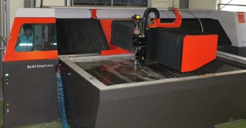
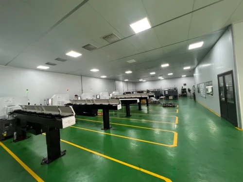
CNCVina's machinery and equipment capacity
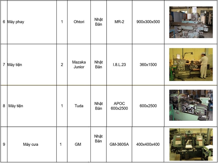
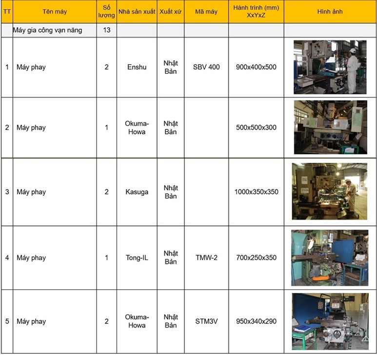
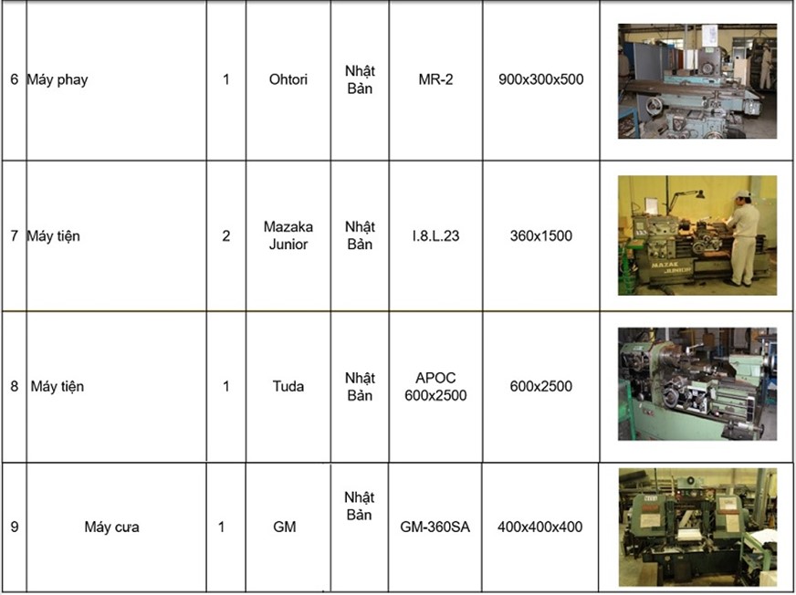
Customers looking for custom design and manufacturing of dedicated fixtures are welcome to contact:
VIETNAM TECHNOLOGY APPLICATION & CNC JOINT STOCK COMPANY
Factory: Song Cung Industrial Cluster, Dong Thap Commune, Dan Phuong District, Hanoi, Vietnam
Office: Rox Tower Building (Rox Center Goldmark City), No. 136 Ho Tung Mau Street, Phu Dien Ward, Hanoi, Vietnam
Telephone: +84.916 63 9355 / +84.915 74 4664
Website: www.cncvina.com.vn ; www.cncvina.net