 Tiếng
Việt
Tiếng
Việt
 Tiếng
Anh
Tiếng
Anh
 Tiếng
Nhật
Tiếng
Nhật




 Tiếng Anh

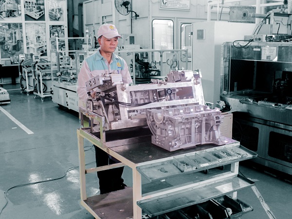
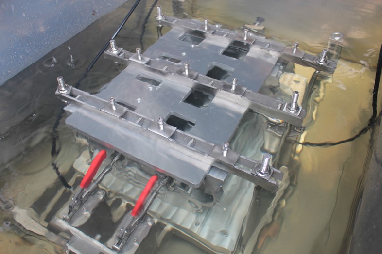
Jig for checking products using compressed air
In production, on-site quality control for each manufacturing step is extremely important. Accurate, fast and timely inspection helps detect and eliminate defective products, ensuring the continuity of production, manufacturing and assembly lines. If the inspection process yields incorrect results, it can cause heavy losses in goods consumption and greatly affect reputation. Manufacturers with quality control processes in place are less likely to face product recalls. The costs associated with these recalls can be high.
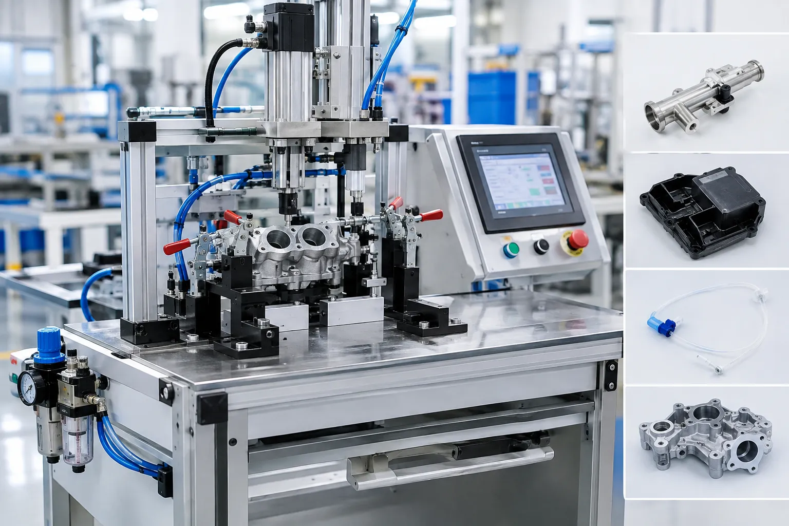
Applying test jigs in product tightness testing, CNCVina provides customers with air tightness testing jigs for the purpose of controlling product errors of details such as engines and machine parts. of cars, motorbikes...
VIETNAM CNC & TECHNOLOGY APPLICATION JOINT STOCK COMPANY
Hotline: +84.916 63 9355 / +84.915 74 4664
Email: Sales01@cncvina.com.vn / Sales03@cncvina.com.vn
Product description

Overview of pneumatic leak testing jigs
A pneumatic leak testing jig is a fixture designed to support the leak testing of components by accurately positioning and clamping the workpiece while connecting it to a compressed air supply and measurement system. During testing, compressed air is introduced into the cavity or passage being tested at a specified pressure. The system then monitors pressure changes or leakage flow over a defined test period to determine whether the component meets the specified leak-tightness requirements.
Pneumatic leak testing is widely used in automotive, motorcycle, electronics, and general mechanical manufacturing, particularly for components and assemblies where leakage control is critical. Depending on the product design and testing requirements, the system can be integrated with pressure sensors, flow measurement devices, or dedicated leak testing equipment. Each jig is designed to match the geometry and testing points of the workpiece, ensuring accurate positioning, reliable sealing, and consistent operation throughout the testing process.
Advantages of pneumatic leak testing jigs
Fast and repeatable testing: The loading, positioning, and testing procedures can be standardized to reduce inspection time for individual components and support production lines requiring frequent leak testing. Actual test time depends on factors such as product volume, test pressure, stabilization time, measurement method, and the allowable leakage rate.
Controlled leak-tightness testing: Pneumatic testing can detect pressure changes or leakage rates exceeding the specified limit when appropriate test conditions are established. Test results can be evaluated against defined technical thresholds for each product rather than relying solely on visual inspection.
Convenient operation: The jig is designed around the shape and testing points of the workpiece, allowing operators to position and clamp components consistently. When integrated with measurement equipment and a control system, test results can be displayed as OK/NG to support efficient product classification.
Suitable for production line integration: A pneumatic leak testing jig can be integrated with compressed air systems, sensors, measurement equipment, and control units to suit different production processes. Depending on the required level of automation, the system can support manual testing or partial automation.
Suitable for a wide range of applications: For products with clearly defined leak testing requirements and repetitive inspection processes, pneumatic leak testing jigs can provide a practical solution in terms of equipment investment and operating costs. The actual cost depends on the jig structure, testing equipment, level of automation, and technical requirements of each application.
Limitations of pneumatic leak testing jigs
Does not replace other inspection methods: Pneumatic leak testing is primarily used to evaluate leak-tightness and leakage performance. It does not replace inspections for dimensions, geometry, appearance, hardness, material defects, or other mechanical properties.
Requires precise control of test conditions: Test pressure, stabilization time, measurement time, temperature, and measurement equipment accuracy can all affect test results. These parameters must therefore be properly established and controlled according to the technical requirements of each product.
High sealing performance is required from the jig: During testing, the jig itself and all connection points must provide reliable sealing to minimize unintended leakage. For products with multiple ports, internal cavities, or complex geometries, designing the positioning, clamping, and sealing mechanisms can be more challenging.
Detection capability depends on the testing method and equipment: Not all pneumatic leak testing systems provide the same level of leakage detection sensitivity. Detection capability depends on the testing method, pressure, product volume, measurement equipment, test duration, and allowable leakage limit. For applications requiring the detection of very low leakage rates, dedicated leak testing equipment may be required.
Technical specifications of pneumatic leak testing jigs
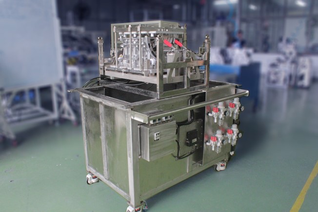
| Specification | Details |
|---|---|
| Overall dimensions | 2,500 (L) × 1,500 (W) × 1,500 (H) mm |
| Working height | 950 mm |
| Machine construction materials | SUS304 and A6061 |
| Number of operators | 2 operators |
| Power supply | Single-phase / 220 V |
| Air pressure | 0.4–1 MPa |
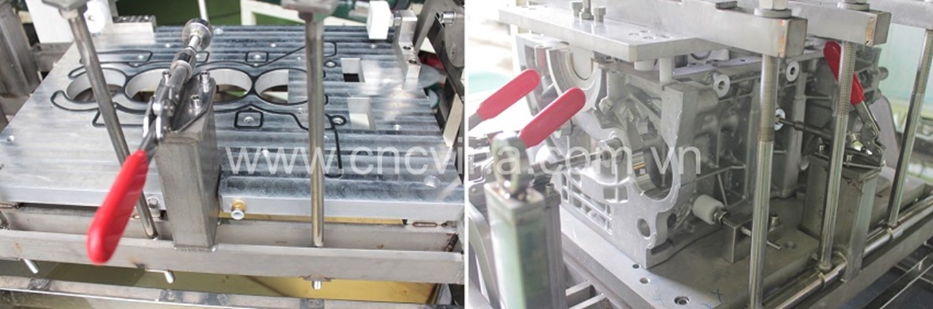
Structure and operating principle of pneumatic product inspection Jig
Structure
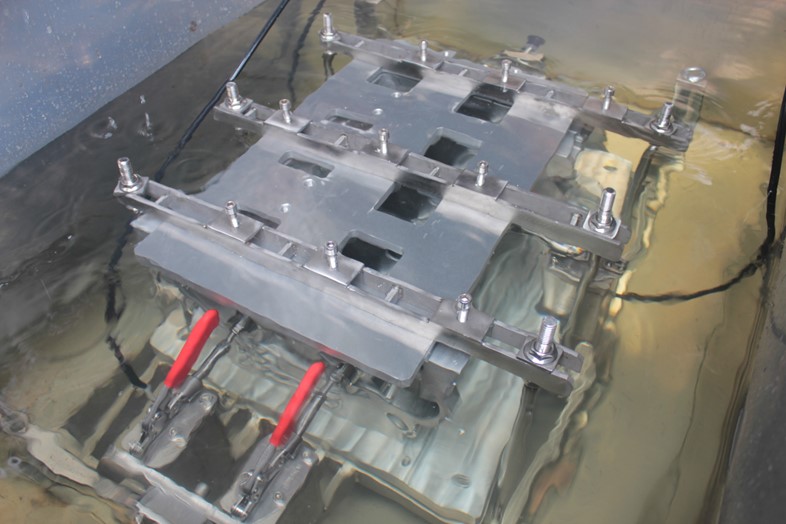
Main components of a pneumatic leak testing jig
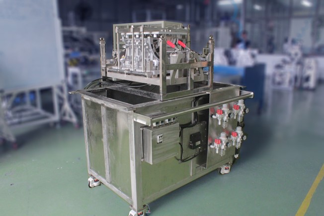
A pneumatic leak testing jig is designed to accurately position and clamp the workpiece while supporting leak-tightness testing by introducing compressed air into the component. With an integrated test water tank, jig lifting and 180° rotation mechanism, the operator can directly observe air bubbles generated at leakage points during the test. Depending on the component structure and inspection requirements, the functional assemblies can be designed and adjusted accordingly to ensure stable workpiece positioning and consistent leak testing. The main assemblies of the system include:
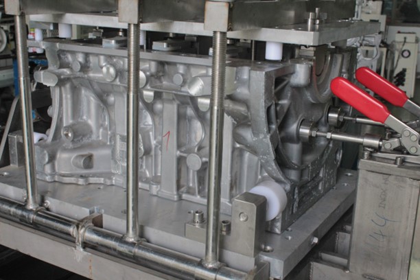
Jig clamping and worktable assembly: Positions and securely clamps the workpiece throughout the air supply and testing process. The jig structure is designed according to the geometry of each component and the locations requiring inspection.
Pneumatic system: Supplies compressed air to the workpiece at the test pressure specified by the technical requirements. The system may include pressure regulators, valves, pneumatic tubing, and suitable air fittings.
Test water tank assembly: Provides the area for leak testing by immersing the workpiece in water. When a component has a leak, escaping air may form bubbles on the surface, helping the operator identify the leakage location.
Jig lifting and 180° rotation assembly: Facilitates loading and unloading the workpiece from the test water tank while allowing the inspection angle to be changed during testing. This mechanism is particularly useful for components with multiple inspection points or surfaces that need to be observed from different directions.
Inspection lighting assembly: Provides adequate illumination in the testing area, allowing the operator to clearly observe the workpiece surface and air bubbles generated in the water tank.
Operating principle of the pneumatic leak testing jig
Operating principle of the pneumatic leak testing jig
The jig operates by introducing compressed air into the cavity or passage to be tested and then immersing the workpiece in a water tank to observe any leakage. When the workpiece is properly sealed, the compressed air is retained inside the component without producing a visible stream of air bubbles on the surface. Conversely, if the component has an opening or an inadequate sealing point, air escapes and forms bubbles in the water. The inspection process can be carried out as follows:
Step 1: Workpiece loading and positioning
Place the workpiece onto the clamping jig on the worktable, align it to the specified position, and secure it in place. Air connection points and sealing locations are configured according to the structure of each workpiece.
Step 2: Compressed air supply
Compressed air is supplied to the workpiece and regulated to the test pressure specified by the technical requirements. With the described configuration, the pressure can be adjusted within a range of 0.2–1 MPa, depending on the inspection procedure and the requirements of each workpiece.
Increasing the pressure from 0.2 MPa to 1 MPa should not be understood as a mandatory procedure for every product. The actual test pressure must be determined based on the product design, material, allowable pressure limits, and applicable inspection standards.
Step 3: Immersion in the test water tank
After the workpiece has been pressurized and the required test conditions have been reached, the lifting mechanism lowers the clamping jig into the water tank. The workpiece is immersed to an appropriate depth so that potential leakage areas remain within the inspection zone.
Step 4: Jig rotation and leak observation
The rotation mechanism changes the orientation of the workpiece, allowing different areas of the component to be inspected. The operator observes the workpiece surface using the integrated inspection lighting system.
No abnormal air bubbles: The workpiece is considered to pass the water immersion leak test according to the specified inspection criteria.
Continuous bubbles or bubbles appearing at a specific location: This indicates a potential leak in the corresponding area. The workpiece should then be classified for further inspection or corrective action in accordance with the applicable quality control procedure.
After the inspection cycle is completed, the jig is raised out of the water tank, the workpiece is removed from the fixture, and the inspected component is transferred to the next process. The same procedure is repeated for subsequent workpieces to maintain consistent inspection conditions throughout production.
Note: The leak detection capability of the water immersion method depends on factors such as test pressure, stabilization time, observation time, leak size and location, and the sealing condition of the workpiece. Therefore, OK/NG acceptance criteria should be established based on specific technical requirements rather than relying solely on a fixed test pressure.
Applications of pneumatic leak testing jigs
Pneumatic leak testing jigs are used to inspect the leak-tightness of components and assemblies with internal cavities, passages, or areas requiring leakage control. The use of dedicated fixtures helps securely position the workpiece, standardize the compressed air supply process, and support repeatable inspection in a production environment.
Automotive industry
In the automotive industry, pneumatic leak testing jigs can be used for components and assemblies that require leakage control, such as certain types of pipes, housings, hollow components, fluid-carrying assemblies, and other parts requiring leak-tightness verification. Depending on the product structure, the jig can be designed with dedicated clamping mechanisms, air connection points, and sealing locations. For components with multiple inspection areas, the lifting and rotation mechanisms allow a wider inspection area to be covered without removing the workpiece from the jig.
Electronics industry
In electronics manufacturing, pneumatic leak testing can be applied to housings, enclosures, or assemblies where control of water, dust, or external environmental ingress is required. The jig is designed according to the product geometry to ensure stable clamping and sealing points throughout the inspection process. For products requiring a higher level of leak-tightness control, the water immersion method can be combined with or replaced by dedicated leak detection equipment, depending on the applicable technical standards.
Medical device industry
For medical devices and equipment, leak-tightness control is an important requirement for components containing air or fluid passages, as well as cavities that need to be protected against leakage. A dedicated testing jig can support stable workpiece positioning and standardized inspection procedures. Certain tubular components, housings, and assemblies can be tested using methods selected according to their characteristics and the manufacturer's quality requirements.
Mechanical manufacturing and fabrication
In mechanical manufacturing and fabrication, pneumatic leak testing jigs can be applied to a wide range of hollow components, castings, welded parts, piping, and assemblies requiring leakage control. For welded components, the inspection method can help identify leakage at weld seams or joint areas when suitable test conditions are established. For hollow cast components, compressed air and water immersion testing can be used to detect leakage caused by casting defects or other discontinuities. However, leak-tightness testing evaluates only specific characteristics related to the leakage performance of a component. Other requirements, such as dimensions, geometric tolerances, surface quality, hardness, and mechanical properties, still need to be verified using appropriate measurement methods and dedicated inspection equipment.
Custom design and manufacturing of product inspection jigs
Each product has different geometry, dimensions, connection points, and inspection requirements. Therefore, the jig should be designed specifically for the intended application rather than based on a fixed configuration for all products. Factors such as the positioning method, clamping mechanism, sealing points, air supply lines, test pressure, inspection time, test tank, and operating method should all be considered during the design process. With experience in machine design and manufacturing, CNC VINA provides custom design and manufacturing solutions for pneumatic leak testing jigs based on the characteristics of each product and the customer's production process. From mechanical design and fixture fabrication to pneumatic system integration, lifting mechanisms, and final testing, each solution can be developed according to the actual technical requirements of the production line.
For customers looking for custom pneumatic leak testing jig design and manufacturing, please contact:
CNC VIETNAM TECHNOLOGY APPLICATION & CNC JOINT STOCK COMPANY
Factory: Song Cung Industrial Cluster, Dong Thap Commune, Dan Phuong District, Hanoi, Vietnam.
Office: Rox Tower Goldmark City, 136 Ho Tung Mau Street, Phu Dien Ward, Hanoi, Vietnam.
Tel: +84.915 74 4664 / +84.915 74 0880
Fax: +84.24.37805007
Website: www.cncvina.com.vn ; www.cncvina.net