 Tiếng
Việt
Tiếng
Việt
 Tiếng
Anh
Tiếng
Anh
 Tiếng
Nhật
Tiếng
Nhật




 Tiếng Anh

Pneumatic leak testing jigs
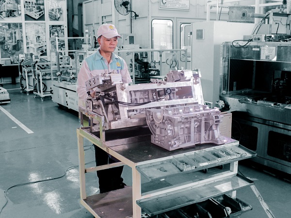
Pneumatic leak testing jigs are among the inspection solutions designed and manufactured by CNC-VINA for a wide range of manufacturing applications, particularly those requiring leak-tightness control for engines, assembled components, plastic bottles, hollow products, plastic injection molds, blow molds, and other components with internal cavities or passages requiring leak inspection. Each jig is designed according to the product geometry, inspection points, and technical requirements to ensure stable workpiece positioning and support a consistent inspection process before the product proceeds to the next production stage.
VIETNAM CNC & TECHNOLOGY APPLICATION JOINT STOCK COMPANY
Hotline: +84.916 63 9355 / +84.915 74 4664
Email: Sales01@cncvina.com.vn / Sales03@cncvina.com.vn
Product description

Pneumatic leak testing jigs are among the inspection solutions designed and manufactured by CNC-VINA for a wide range of manufacturing applications, particularly those requiring leak-tightness control for engines, assembled components, plastic bottles, hollow products, plastic injection molds, blow molds, and other components with internal cavities or passages requiring leak inspection. Each jig is designed according to the product geometry, inspection points, and technical requirements to ensure stable workpiece positioning and support a consistent inspection process before the product proceeds to the next production stage.
Overview of pneumatic leak testing jigs
A pneumatic leak testing jig (air leak testing jig) is a dedicated fixture used to verify the leak-tightness of products, components, and assemblies where leakage control is required. Typical applications include plastic bottles, engine leak testing, assembled components, molds, and various types of hollow products. Depending on the product structure and inspection requirements, the jig can be configured with positioning mechanisms, clamping mechanisms, air supply connections, and dedicated sealing points. During testing, the workpiece is securely positioned on the jig and pressurized according to the specified test conditions. Depending on the inspection method, the system can be integrated with pressure gauges, pressure sensors, or a water immersion test tank to support leak detection and identification.
CNC-VINA manufactures pneumatic leak testing jigs using CNC machining according to specific product and production requirements. The dedicated fixture is designed to suit the characteristics of each workpiece and the actual production process. By standardizing workpiece loading, positioning, clamping, and air supply operations, the jig helps reduce variation during inspection and supports early detection of products that may not meet the specified leak-tightness requirements. This enables manufacturers to control product quality at the inspection stage and minimize the risk of non-conforming products proceeding to subsequent production processes.
Structure and operating principle of pneumatic leak testing jigs
Structure of a pneumatic leak testing jig
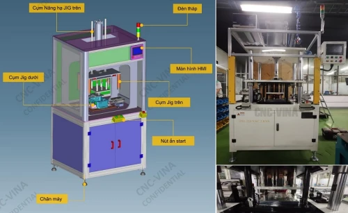
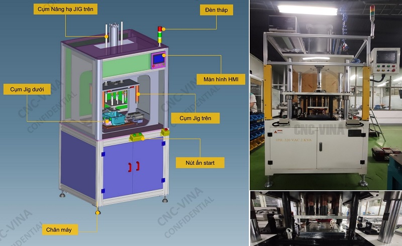
Depending on the requirements of each product, a pneumatic leak testing jig can be designed with different functional assemblies. A basic configuration may include the following main assemblies:
- Frame assembly: Serves as the main structural framework of the equipment, supporting and securing the functional assemblies while maintaining stability during operation and inspection.
- Pressing assembly: Applies clamping force to hold the workpiece securely at the inspection position, ensuring stable positioning during air pressurization and leak testing.
- Jig assembly: Designed according to the geometry and dimensions of the workpiece, this assembly performs positioning and clamping functions while providing the necessary air connection and sealing points for the inspection process.
Pneumatic leak testing jigs designed and manufactured by CNC-VINA can be configured according to individual product specifications and production line requirements. The jig structure can be optimized for convenient workpiece loading, unloading, fixture replacement, and changeover between different product models. For production lines handling multiple product models, interchangeable jig modules or fixture assemblies can help reduce changeover time and improve production flexibility.
Operating principle of the pneumatic leak testing jig
A pneumatic leak testing jig operates by introducing compressed air into the cavity or passage to be inspected and then monitoring pressure changes or detecting leakage according to the selected test method. The workpiece is first positioned and securely clamped on the jig, after which the air connection and sealing points are established according to the configuration of the specific product. Once the workpiece has been properly sealed, compressed air is supplied at the specified test pressure. Depending on the inspection method, leak-tightness can be evaluated based on pressure decay, leakage flow rate, or visible air bubbles when the workpiece is immersed in water. The test results are then used to determine whether the workpiece meets the specified leak-tightness criteria. Parameters such as test pressure, stabilization time, test duration, and allowable leakage rate should be established based on the product characteristics, material, and applicable technical standards.
Operating procedure
Step 1: Workpiece loading
The operator places the workpiece to be inspected onto the support jig and aligns it to the designated position according to the fixture design.
Step 2: Safety condition activation
After positioning the workpiece, the operator moves their hands away from the operating area of the mechanism and the inspection zone. The system allows the inspection cycle to start only after the required safety conditions have been satisfied.
Step 3: Workpiece detection
A photoelectric sensor detects the presence of the workpiece and sends a signal to the control system to confirm the conditions required to start the inspection cycle.
Step 4: Pressing and workpiece clamping
The pressing cylinder actuates the pressing mechanism to secure the workpiece against the fixed jig assembly. This mechanism maintains stable workpiece positioning throughout the air supply and leak testing process.
Step 5: Air supply and leak testing
The air supply jig introduces compressed air into the cavity being tested. When the internal pressure reaches 0.5 MPa, the pressure switch monitors the pressure for approximately 10 seconds, according to the preset test duration. During this period, the system monitors the pressure condition to determine whether the workpiece meets the specified leak-tightness criteria.
Step 6: Marking the inspected workpiece
When the workpiece meets the inspection criteria, the marking mechanism operates to identify its inspected status.
Step 7: Cycle completion and workpiece removal
After the inspection cycle is completed, the pressing cylinder returns to its standby position. Depending on the actual machine configuration, an air-blow mechanism may be used to remove dust or clean the inspection area. The operator then removes the workpiece from the jig and transfers it to the next production process. The same procedure is repeated for subsequent workpieces to maintain consistent inspection conditions throughout production.
Technical specifications of the leak testing machine
| Specification | Details |
|---|---|
| Machine dimensions | 300 × 300 × 760 mm |
| Power supply | AC 220 V, 50 Hz |
| Air supply pressure | 0.5 MPa |
| Cycle time | 10 seconds |
| Workpiece-to-jig installation tolerance | ±0.1 mm |
| Parallelism tolerance during pressing | ±0.2 mm |
Note: The 0.5 MPa pressure specified above refers to the air supply pressure for the described machine configuration. The actual test pressure for each product should be determined based on the product's technical requirements and allowable pressure limits.
Dandory procedure for mold changeover
Mold removal procedure
Step 1: When changing the product model, press the DOWN button to lower the cylinder until the upper and lower molds come into contact.
Step 2: Remove the bolts at both ends of the mold stopper bar, then use the mold removal hook to pull out the mold spacer bar.
Step 3: Press the UP button to raise the cylinder. Then remove the positioning pins and bolts securing the lower jig plate to the machine table.
Step 4: Use a forklift or other suitable handling equipment to remove the complete mold assembly from the machine and transfer it to the designated standby position for the next model changeover.
Mold installation procedure
Step 1: Move the complete mold assembly from the standby position to the designated jig mounting position on the machine table.
Step 2: Install the positioning pins and bolts to secure the lower jig plate to the machine table.
Step 3: Press the DOWN button to lower the cylinder and align the upper mold assembly with the lower jig plate.
After completing mold installation, check the mounting position, mold stability, and connection points before returning the machine to operation.
Maintenance of the leak testing machine
To maintain stable operation and minimize variation during inspection, the machine should be cleaned and maintained periodically according to its actual operating conditions.
Daily air pressure check: Check the pressure gauge to ensure that the supplied air pressure remains within the required operating range.
Cleaning and lubrication of moving mechanisms: Clean the surfaces and apply appropriate lubricant to the slide rails, cylinders, and other moving mechanisms. Inspect and realign the mechanisms when necessary, particularly after extended operation or according to the machine's preventive maintenance schedule.
Weekly jig cleaning: Use clean cotton or a suitable cloth moistened with an appropriate alcohol-based cleaner to clean the jig surfaces, particularly the workpiece contact, sealing, and positioning areas.
Inspection of sealing points: Periodically inspect seals, gaskets, air fittings, and contact surfaces for wear, damage, or deterioration that may affect sealing performance.
Custom design and manufacturing of pneumatic leak testing jigs
Pneumatic leak testing jigs should be designed according to the geometry, dimensions, sealing points, and inspection requirements of each product. Depending on the required level of automation, the system can integrate workpiece detection sensors, pressing mechanisms, air supply systems, pressure switches, marking mechanisms, and other supporting functions to meet the inspection requirements of the production line. CNC VINA provides custom design and manufacturing of pneumatic leak testing jigs, inspection fixtures, automated inspection machines, and inspection systems, covering mechanical design, jig fabrication, pneumatic mechanism integration, and control system integration according to the requirements of each application.
Customers interested in the design and manufacturing of pneumatic leak testing jigs, inspection fixtures, and automated inspection machines are welcome to contact:
CNC VIETNAM TECHNOLOGY APPLICATION & CNC JOINT STOCK COMPANY
Factory: Song Cung Industrial Cluster, Dong Thap Commune, Dan Phuong District, Hanoi, Vietnam.
Office: Rox Tower (Rox Center Goldmark City), No. 136 Ho Tung Mau Street, Phu Dien Ward, Hanoi, Vietnam.
Tel: +84.916 63 9355 / +84.915 74 4664
Website: www.cncvina.com.vn ; www.cncvina.net